
Apparatus and Method for Use In Slim Hole Wells

a technology of apparatus and wellbore, which is applied in the direction of drilling casings, wellbore/well accessories, pipes, etc., can solve the problems of affecting the sealing performance of the well, so as to improve the sealing performance.

Active Publication Date: 2014-01-02
SCHLUMBERGER TECH CORP
View PDF7 Cites 21 Cited by
  • Summary
  • Abstract
  • Description
  • Claims
  • Application Information

AI Technical Summary

Benefits of technology

The patent describes methods and apparatus for constructing a wellbore using a liner and casing. By directly connecting the liner to the casing, a slimmer wellbore can be created, allowing for the liner to have a larger inner diameter. The internal diameter of the casing is tapered to prevent a hydraulic lock and ensure smooth operation. The parts are also designed with seals to improve sealing performance between the liner and casing. Additionally, a wear protection cover is provided to protect the casing from wear and tear. The cover is attached to the casing with a fastening arrangement that ensures a tight seal and can prevent debris from entering the space between the cover and casing. The methods and apparatus described in the patent reduce the risk of hydraulic lock and improve wellbore construction efficiency.

Problems solved by technology

However, in certain environments, such as for example, in deepwater environments, long casing is often too heavy to risk as a single deployment.
Also, Equivalent Circulating Density (ECD) with a long string can be too high causing the potential for circulation loss zones.
Such high pressures may be high enough to cause the drilling mud to be pumped into the formation being drilled and thus cause damage or even destruction to the reservoir.
As well design becomes more challenging, due to longer step outs and deeper targets, and reservoirs become depleted, there are more reasons to design well construction with critical casing strings run as liners.
Also, the smaller diameter of the production tubing increases the velocity of the oil and gas.
A major disadvantage of this known tieback connection is that the majority of the inside length of the PBR is exposed and is susceptible to damage as other downhole tools are run into the wellbore.
This can cause damage that reduces the sealing ability of the PBR.
Also, drilling debris can degrade the PBR sealing surfaces.
In addition, it is known that associated components, such as tie back stingers, seal stems and packers can leak, particularly in harsh environments.
Over time this movement can cause the seals to wear and ultimately to fail.
This is regarded to be one of the major limitations of a conventional PBR.
Elastomeric seals are prone to damage during deployment and are inherently prone to wear over time and thus cannot be relied upon to last the life of well.
In addition they will be worn due to relative movement when the well temperature changes during production and shut in cycles.
Hence, elastomeric seals are no longer considered suitable for a well barrier in some areas.
Still furthermore, the PBR is generally short (3-4 m) causing spacing out of the tieback string to be sometimes difficult to achieve successfully first time.
In deep wells, especially subsea wellheads, this can have a substantial time and cost implication.
It is usually not possible to lengthen the PBR due to the design of the liner hanger system.
A PBR is prone to damage and a relatively minor score may compromise the seal.
Furthermore, the use of elastomeric seals in the well barrier envelope is not allowed in certain places, e.g. in the Norwegian sector of the North Sea.
However, while this method eliminates the need to use a PBR connection, it has a major limitation in that for certain wells the annular space between the outer casing string ID and the liner string OD too small to fit the expandable tieback connection.

Method used


Image

  • Apparatus and Method for Use In Slim Hole Wells
  • Apparatus and Method for Use In Slim Hole Wells
  • Apparatus and Method for Use In Slim Hole Wells

Examples


Embodiment Construction

[0054]Embodiments of the present invention will now be described, by way of example only, with reference to the accompanying drawings in which:

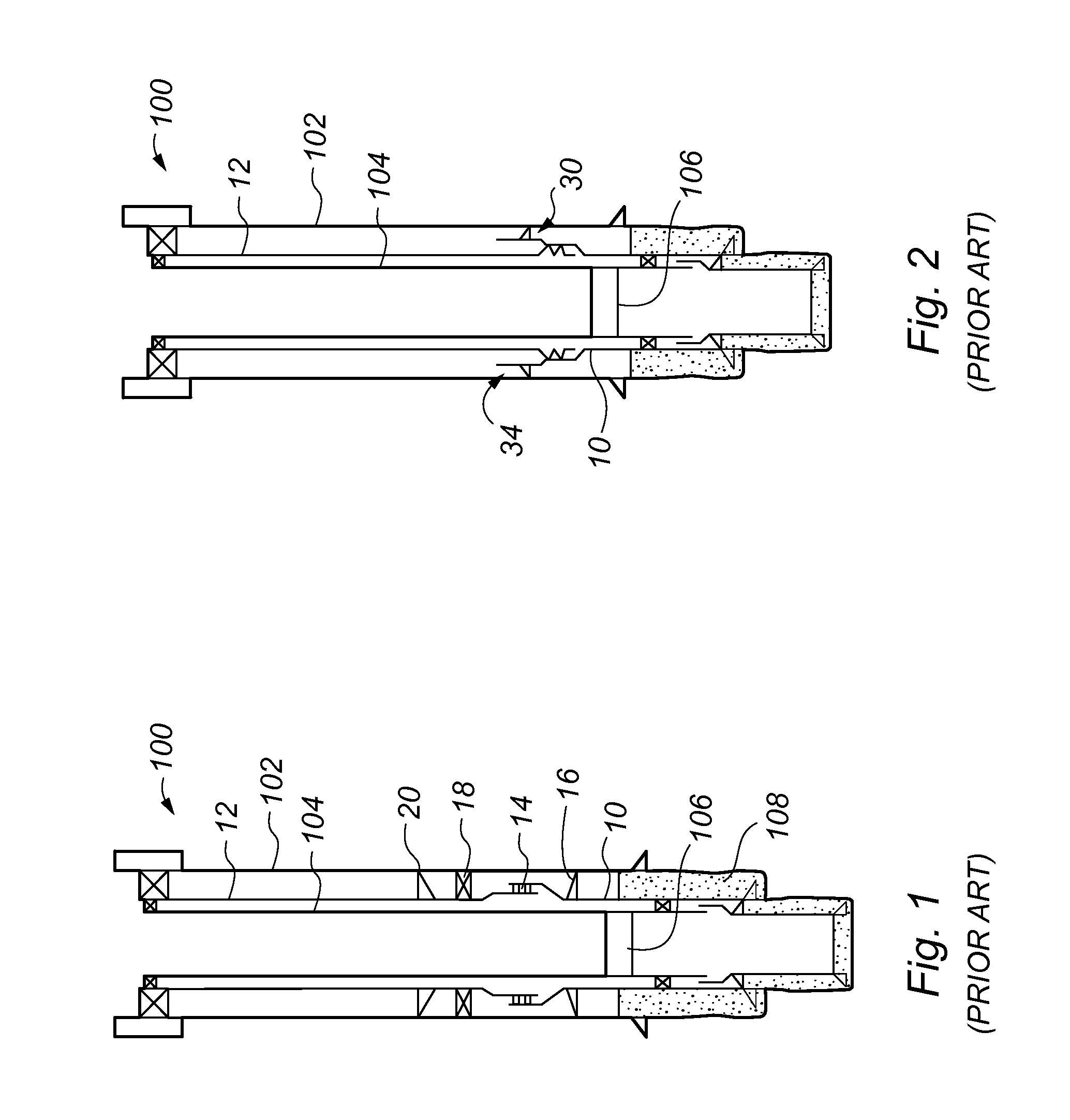
[0055]FIG. 1 is a sectional side view of a method of providing a liner tieback connection according to the prior art;

[0056]FIG. 2 is a sectional side view of a further prior art method of providing a liner tieback connection;

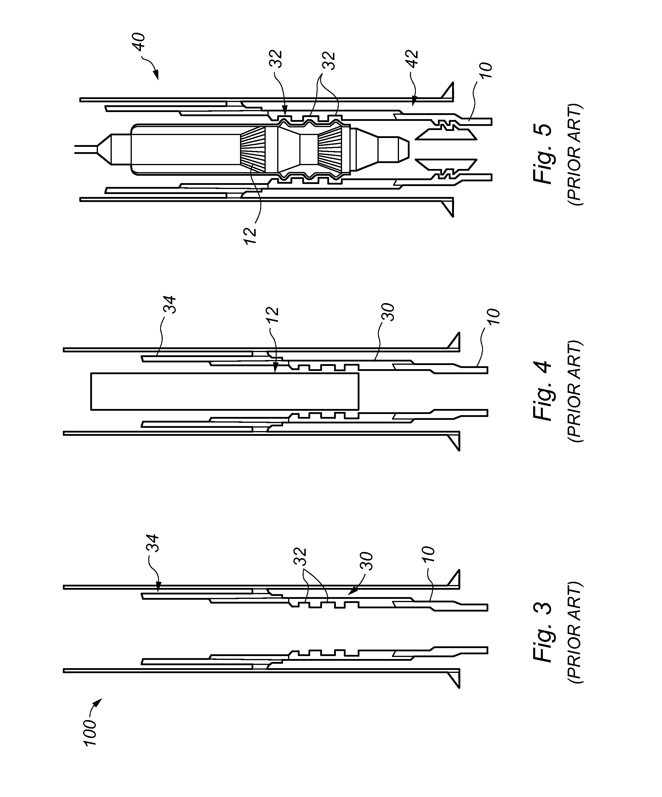
[0057]FIGS. 3 to 5 are sectional side views of stages of the prior art method of FIG. 2;

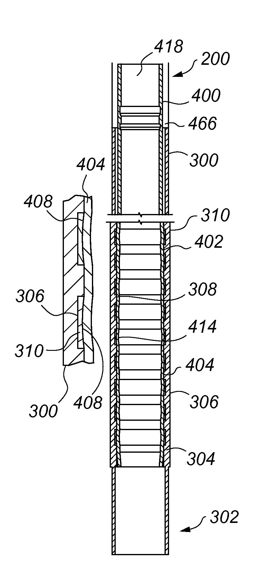
[0058]FIGS. 6 to 9 are sectional side views of a number of different embodiments of a first casing section that can be used in the method of providing a tubular connection according to the present invention;

[0059]FIG. 10 is a sectional side view showing a cover used in conjunction with the first casing section used in the method of the present invention;

[0060]FIGS. 11 to 13 are sectional side views of a part of a portion of a liner for connecting with the first casing section of FIGS. 6 to 10;

[0061]FIGS. 14 to 17 are sectional side vie...


PUM


Abstract

An apparatus and method for providing a tubular connection in the form of a liner tieback connection or a liner hanger in a slim hole well as found in deep wells. When installing the casing sections, a first casing section having a profiled surface distinct from a surface of an adjacent casing section is provided. A liner is run into the first casing section and a part of a portion is radially expanded to morph against the inner surface of the first casing section at the profiled surface and form a sealed joint. Various arrangements of profiled surfaces are provided. The liner may also have a profiled surface. By adapting the casing section to receive the liner directly, a slim hole well construction is achieved.

Description

FIELD OF THE INVENTION[0001]The present invention relates to an apparatus and a method for connecting tubular members in a wellbore and more particularly, though not exclusively, to an apparatus and a method for providing a tieback connection in a slim hole well.BACKGROUND TO THE INVENTION[0002]Wellbores are typically formed by drilling a borehole to a first pre-determined depth and then lining the borehole with a steel casing. Typically, a number of sections of casing of decreasing diameter are used. A first section of casing is lowered into the wellbore and hung from the surface after the well has been drilled to a first designated depth. Cement is then circulated in the annulus between the outer wall of the casing and the borehole. The well is then drilled to a second designated depth and a second section of casing having a smaller diameter is run into the well. This process is typically repeated with additional casing sections of decreasing diameter until the well has been drill...

Claims


Application Information

Patent Timeline
Patent Type & Authority Applications(United States)
IPC IPC(8): E21B19/16
CPCE21B19/16E21B43/101E21B43/103E21B43/106E21B43/108
Inventor GORRARA, ANDREW JOHN JOSEPHO'BRIEN, DANIELWOOD, PETER
Owner SCHLUMBERGER TECH CORP
Learn More