Embolus Removal Device with Blood Flow Restriction and Related Methods

a technology of embolism and removal device, which is applied in the field of clot retrieval and removal devices, can solve the problems of increased risk of bleeding, cumbersome delivery and deployment, and limited use of intravenous t-pa

Inactive Publication Date: 2017-05-04
NEUROVASC TECH
View PDF20 Cites 24 Cited by
  • Summary
  • Abstract
  • Description
  • Claims
  • Application Information

AI Technical Summary

Benefits of technology

[0016]The devices of the present invention can be made from either metallic biocompatible material (such as Nitinol, stainless steel, Co—Cr base alloy, Ta, Ti, etc.) or polymer based biocompatible material (polymers with shape memory effect, PTFE, HDPE, LDPE, Dacron, Polyester, etc.). For ischemic stroke treatment, the expandable treatment member must be flexible enough to negotiate the torturous vasculature of the brain and without modifying the vessel profile at the target location. The profile of the expandable treatment member must be small enough to reach target treatment site as known to artisans.

Problems solved by technology

Intravenous t-PA is currently limited in use because it must be used within a three-hour window from the onset of a stroke and can result in an increased risk of bleeding.
This standard of care leaves room for upgrade, and is only the appropriate approach to treatment for a limited class of individuals, groups and temporally-limited exigent cases.
First, filter-type thrombectomy devices tend to be cumbersome and difficult to deliver and deploy, and a larger-profile guide catheter may be needed to fully remove the embolus. In addition, it is difficult to coordinate precise and predictable movement to position the device properly in the vessel. The device can drift within the vessel, twist, or not be adequately conforming to the vessel wall and, therefore not effective for removing embolus.
Cork-screw guidewire devices can only capture and remove emboli that are firm, or subject to certain mechanical variables such as being held together by itself as one piece.
Cork-screw guidewire devices are not effective in removing particulate matter that may be scattered or broken up.
Stent-like mechanical thrombectomy devices are not capable of capturing small emboli that break off from a large embolus (if any), and can lead to complications such as the blockage of distal smaller vessels, vessel dissection, perforation, and hemorrhage arising as a result of over-manipulation in the vessel.
The disadvantages common to all of the devices described above include, for example: 1) the device may capture an embolus, but then lose grasp of it and migrate / deposit it incidentally into another area of the neurovasculature, creating the potential for a new stroke in a different part of the neurovasculature; 2) the device is not capable of capturing small embolus breaking off from the larger embolus and preventing it from migrating to a more distal area of the neurovasculature; 3) the relative large device profile prevents these devices from treating the distal smaller diameter vessels; and 4) risk of sICH (symptomatic Intra-cerebral Hemorrhage) after intra-arterial clot removal in acute stroke patients.
Other flaws in the current mechanical thrombectomy designs include poor visibility / radiopacity, lack of variation in the delivery portion to enhance and improve deliverability, and lack of coatings or modified surface textures on the treatment portion to enhance embolus affinity, etc.
None of the existing medical mechanical thrombectomy devices address all necessary needs to date.

Method used


Image

  • Embolus Removal Device with Blood Flow Restriction and Related Methods
  • Embolus Removal Device with Blood Flow Restriction and Related Methods
  • Embolus Removal Device with Blood Flow Restriction and Related Methods

Examples


first embodiment

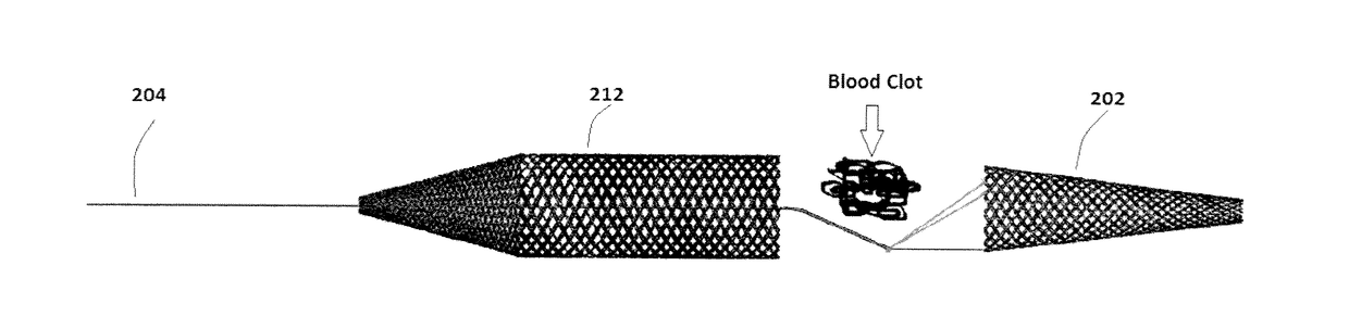
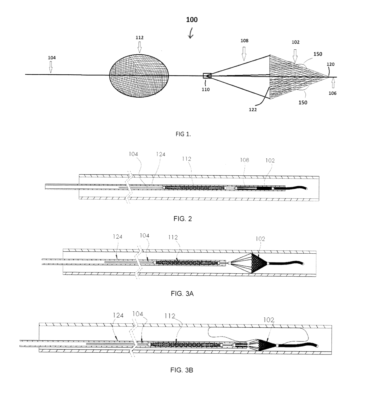
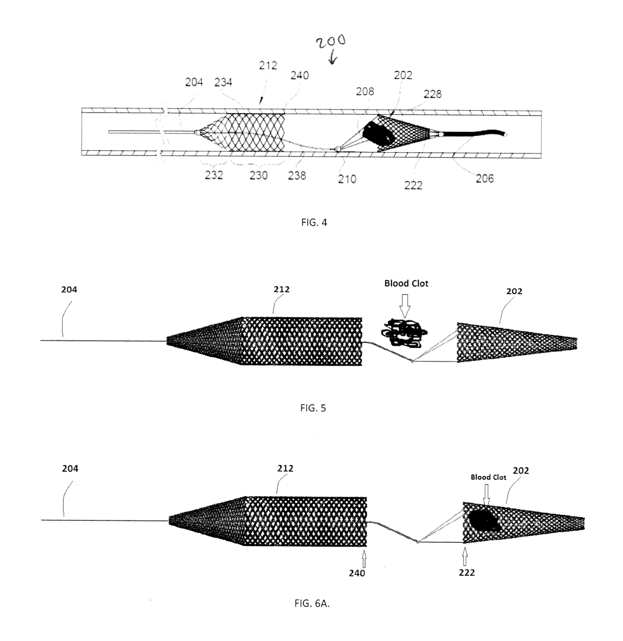
[0063]For example, FIGS. 4-6 illustrate another embodiment of a device 200 for removing emboli and other luminal blockages. The device 200 also has an expandable treatment member 202, a soft distal tip 206 (with marked coil), a delivery wire 204, control arms 208, a hub 210 and a proximal flow restrictor 212 that correspond to the expandable treatment member 102, soft distal tip 106 (with marked coil), delivery wire 104, control arms 108, hub 110 and proximal flow restrictor 112, respectively, for the first embodiment, except for a few differences.

[0064]First, the expandable treatment member 202 has a slightly different configuration. Instead of the conical configuration of the expandable treatment member 102, the expandable treatment member 202 has a frusto-conical body 228 where its distal-most end does not terminate in an apex, but has a small distal opening.

[0065]Second, the proximal flow restrictor 212 has a different configuration, having a body that includes a cylindrical dis...

second embodiment

[0072]FIGS. 7-9 illustrate another embodiment of a device 300 for removing emboli and other luminal blockages. The device 300 is similar to the device 200 in that it also has an expandable treatment member 302, a delivery wire 304, a hub 310 and a proximal flow restrictor 312 that correspond to the expandable treatment member 202, delivery wire 204, hub 210 and proximal flow restrictor 212, respectively, for the second embodiment, except for a few differences.

[0073]First, the expandable treatment member 302 has a different configuration, and can be configured as any of the removal devices disclosed in co-pending United States Publication No. 2015-0150672, filed Jan. 16, 2015, whose entire disclosure is incorporated by this reference as if set forth fully herein. For this reason, there are no control wires 108 / 208.

[0074]Second, the proximal flow restrictor 312 can be essentially the same as the proximal flow restrictor 212 in FIGS. 4-6.

[0075]Third, the hub 310 can function as a marke...


PUM


Abstract

A clot removal device has an expandable treatment member having a distal tip and a proximal end, a delivery wire having a distal end coupled to the proximal end of the expandable treatment member, and a flow restrictor carried along the delivery wire at a location that is separate and proximal from the expandable treatment member. The flow restrictor has a body with a distal section and a proximal section, the distal section being covered and the proximal section being uncovered. The expandable treatment member is moveable relative to the flow restrictor, and can be retracted into the distal section.

Description

RELATED CASES[0001]This application claims priority from U.S. Provisional Application Ser. No. 62 / 249,249, filed on Oct. 31, 2015, and U.S. Provisional Application Ser. No. 62 / 251,069, filed on Nov. 4, 2015, the contents of each of which are incorporated by this reference as if fully set forth herein in their entirety.BACKGROUND OF THE INVENTION[0002]1. Field of the Invention[0003]The present invention generally relates to devices and methods useful for clot retrieval, and removal devices to treat, among other things, ischemic stroke.[0004]2. Description of the Prior Art[0005]Currently, the FDA-approved treatment options for an acute ischemic stroke include intravenous (IV) delivery of clot dissolving medicine and mechanical thrombectomy.[0006]For treatment use, clot dissolving medicine, such as the thrombolytic agent (Tissue Plasminogen Activator (t-PA)), is injected into the vasculature to dissolve blood clots that are blocking blood flow to the neurovasculature. Intravenous t-PA ...

Claims


Application Information

Patent Timeline
Patent Type & Authority Applications(United States)
IPC IPC(8): A61B17/221
CPCA61B17/221A61B2017/22079A61B2017/2215A61B2017/00867A61B2090/3966A61B90/39A61B2017/22038A61B17/12131A61F2/013A61M25/0021A61B17/12109A61B2017/2212A61B2017/1205A61B2017/2217A61F2230/0067A61F2002/016A61B2017/22051A61B2017/00893A61M2025/0042
Inventor MA, JIANLU
Owner NEUROVASC TECH
Why Eureka
Try Eureka