Axial flow type cooling fan with shrouded blades

a cooling fan and axial flow technology, which is applied in the direction of positive displacement liquid engines, piston pumps, fluid engines, etc., can solve the problems of vortex shedding noise, cooling fans are disadvantageous for a flatter shape, the air flow is increased. , the effect of improving rotational stability

Inactive Publication Date: 2007-03-20
IND TECH RES INST
View PDF2 Cites 63 Cited by
  • Summary
  • Abstract
  • Description
  • Claims
  • Application Information

AI Technical Summary

Benefits of technology

[0011]It is therefore an object of the present invention to provide an axial flow type cooling fan with an increased area of air flow, resulting in increased air flow, better rotational stability and allowing for a flatter shape, so that a more compact shape, lower noise, longer lifetime and more versatility for use in small devices like pen computers are achieved. The present invention comprises: an upper casing and a lower casing, enclosing an inner space; a rotor assembly in the inner space, having a central shaft, a plurality of blades and a peripheral ring, which together form an integral body; and a driving unit, driving a rotational movement of the rotor assembly. The driving unit further comprises electric coils on the upper or lower casings and permanent magnets on a peripheral rim of the rotor assembly. By this arrangement, increased air flow at better rotational stability and reduced drag is achieved.
[0012]Another object of the present invention is to provide an axial flow type cooling fan with better rotational stability.
[0013]A further object of the present invention is to provide an axial flow type cooling fan which prevents air from escaping from far edges of blades.
[0014]A further object of the present invention is to provide an axial flow type cooling fan which allows for a flat design.

Problems solved by technology

However, due to limitations of structure, always having a motor with a shaft, increasing air flow and reducing drag is fraught with difficulties.
Direct driving of the shaft of the rotor results in the following problems: (1) Air flow is achieved only in a narrow area.
(2) Supports of the driving unit in the air flow result in vortex shedding and noise.
(3) Large quantities of air escape from edges of ventilator blades.
This design of a cooling fan is disadvantageous for a flatter shape.

Method used


Image

  • Axial flow type cooling fan with shrouded blades
  • Axial flow type cooling fan with shrouded blades
  • Axial flow type cooling fan with shrouded blades

Examples


Embodiment Construction

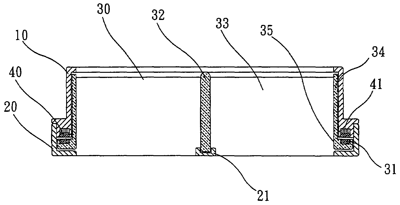
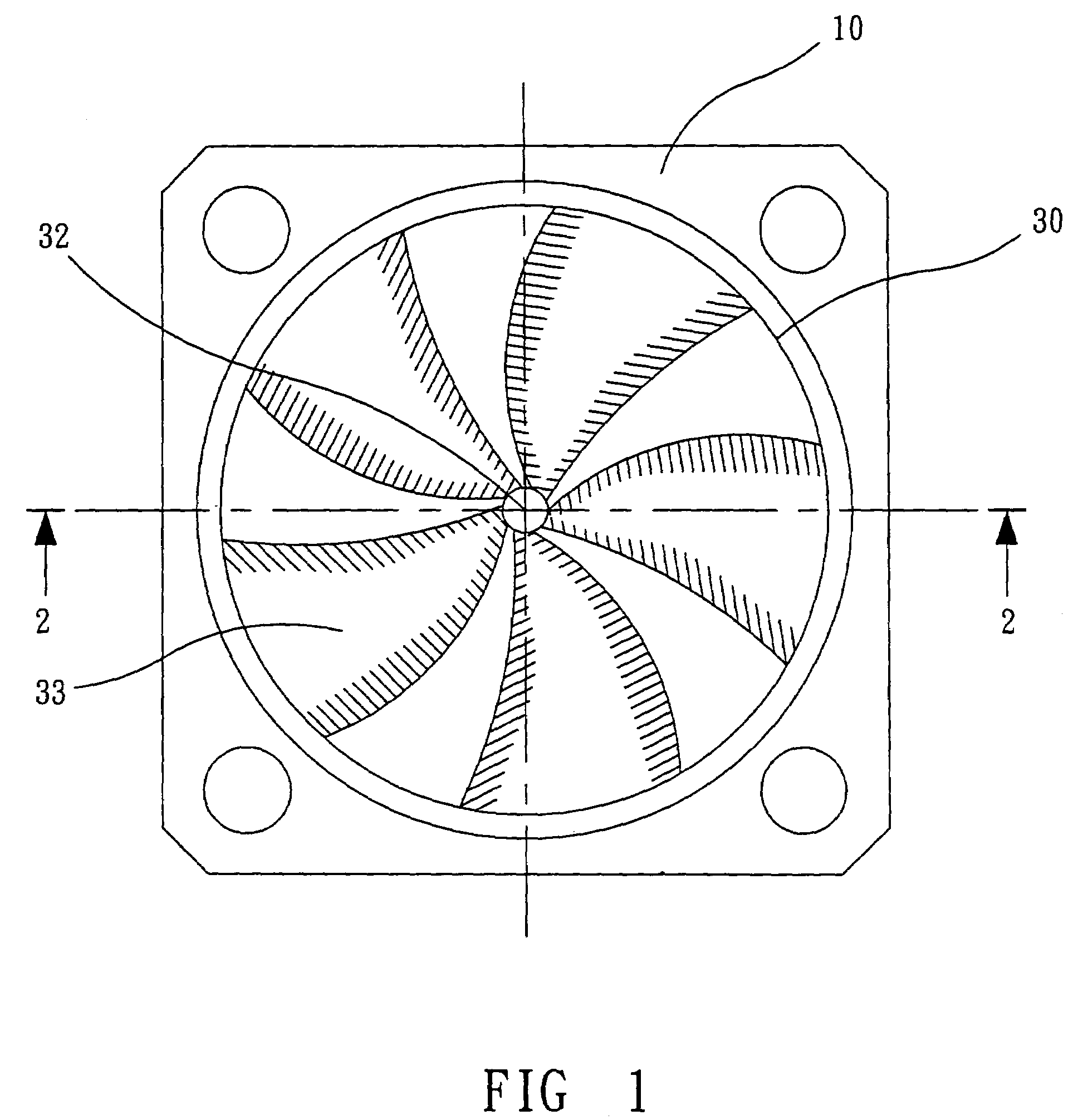
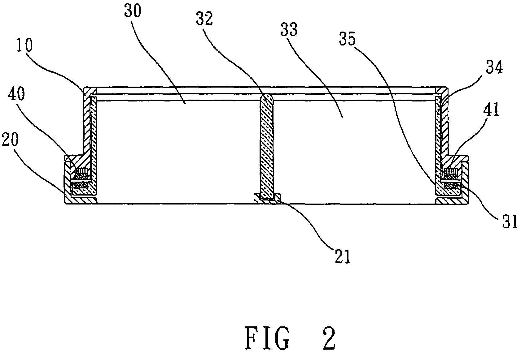
[0016]As shown in FIGS. 1 and 2, the axial flow type cooling fan of the present invention comprises: an upper casing 10; a lower casing 20; a rotor assembly 30; and a driving unit 40, driving a rotational movement of the rotor assembly 30.

[0017]The upper and lower casings 10, 20 are fastened to each other by bolts or hooks, forming a complete enclosure for the rotor assembly 30 and the driving unit 40.

[0018]The rotor assembly 30 has a central shaft 32, carrying a plurality of blades 33. The blades 33 have outer edges that carry a peripheral ring 34. A peripheral rim 35 extends from the peripheral ring 34 outward. Permanent magnets 31 are attached to the peripheral rim 35.

[0019]The driving unit 40 drives the rotating movement of the rotor assembly 30 with respect to the upper and lower casings 10, 20. The driving unit 40 has coils 41, which are placed facing the permanent magnets 31 of the rotor assembly 30.

[0020]When an electric current passes through the coils 41 of the driving uni...


PUM


Abstract

An axial flow type cooling fan, comprising an upper casing, a lower casing, a rotor assembly, and a driving unit. The lower casing and the upper casing enclose an inner space. The rotor assembly is housed in the inner space and performs a rotational movement. The rotor assembly further comprises a plurality of blades, attached to a central shaft and having a peripheral ring, from which a peripheral rim extends outward. The driving unit has electric coils on the upper or lower casings and permanent magnets on the peripheral rim, causing the rotational movement of said rotor assembly. By the arrangement of these structural parts, an increased area of air flow and consequently increased air flow are attained, while drag and noise are reduced.

Description

FIELD OF THE INVENTION[0001]The present invention relates to an axial flow type cooling fan with shrouded blades, characterized by: (1) having a driving unit which comprises electric coils on a casing and permanent magnets on a peripheral rim of a rotor assembly, (2) having the electric coils placed either on an upper casing or a lower casing or both upper and lower casings, (3) the rotor assembly having a central shaft, a plurality of blades and a peripheral ring, which form an integral body. By the arrangement of its structural parts, the present invention offers (1) an increased area of air flow and consequently increased air flow, no escaping of air from blade edges. (2) increased rotational stability at reduced noise, and (3) implementability of a flat shape, making the present invention suitable for notebook computers.DESCRIPTION OF RELATED ART[0002]Microprocessors used in a computer are undergoing a fast development to ever greater performance, accompanied by an ever increasi...

Claims


Application Information

Patent Timeline
Patent Type & Authority Patents(United States)
IPC IPC(8): F04B17/00F04D25/06
CPCF04D25/066
Inventor KUO, CHII-RONCHANG, CHIA-YANGWEY, TZENG WUU
Owner IND TECH RES INST
Why Eureka
Try Eureka