
Thermal fan without inverse flow characteristic

A heat dissipation fan without backflow technology, which is applied to components of pumping devices for elastic fluids, non-variable pumps, machines/engines, etc., and can solve the problem that the heat dissipation effect of the heat dissipation fan 1 is damaged and the air flow cannot be effectively and smoothly Circulation and other issues

Inactive Publication Date: 2009-08-19
ASIA VITAL COMPONENTS SHENZHEN CO LTD
View PDF4 Cites 0 Cited by
  • Summary
  • Abstract
  • Description
  • Claims
  • Application Information

AI Technical Summary

Problems solved by technology

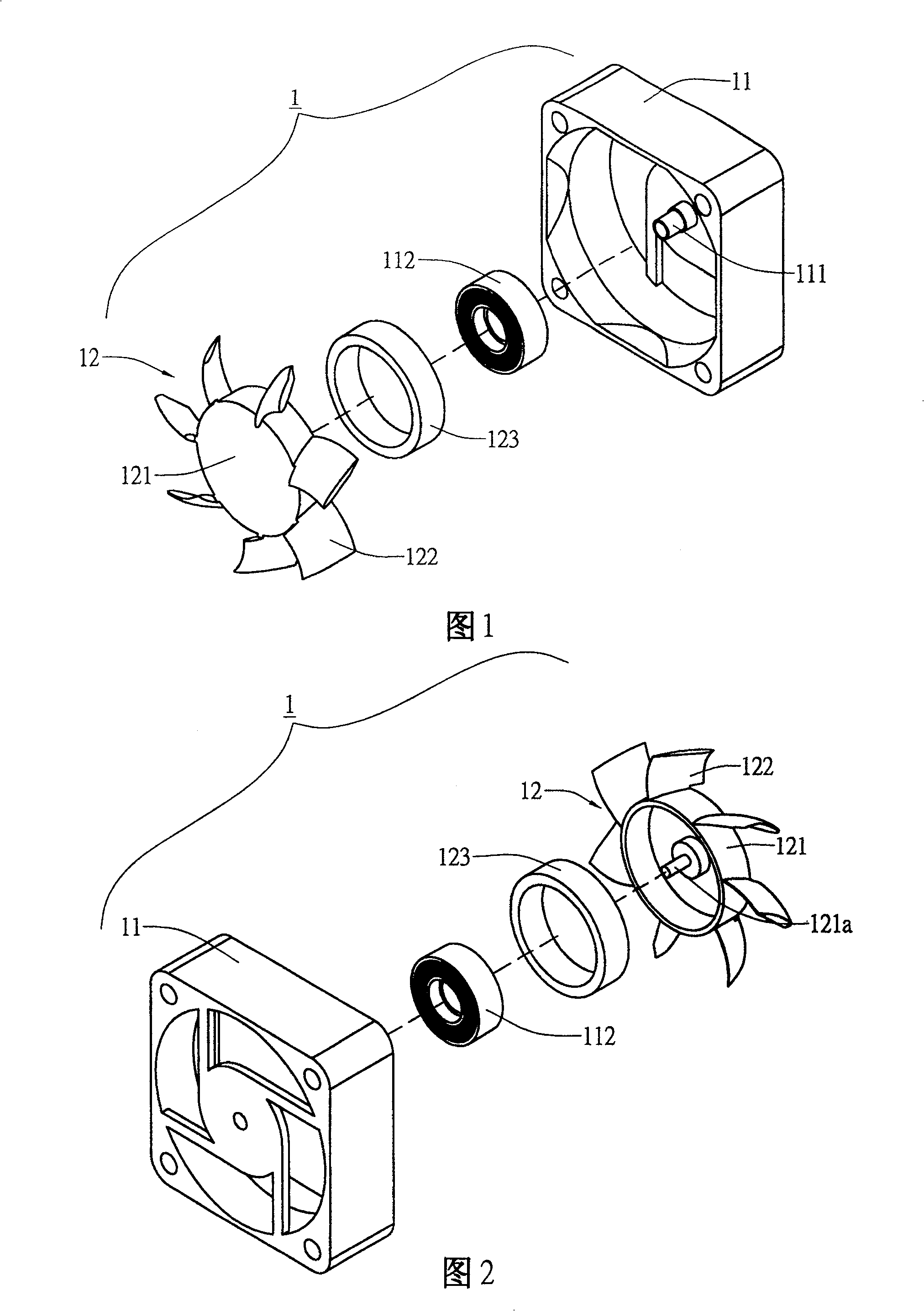
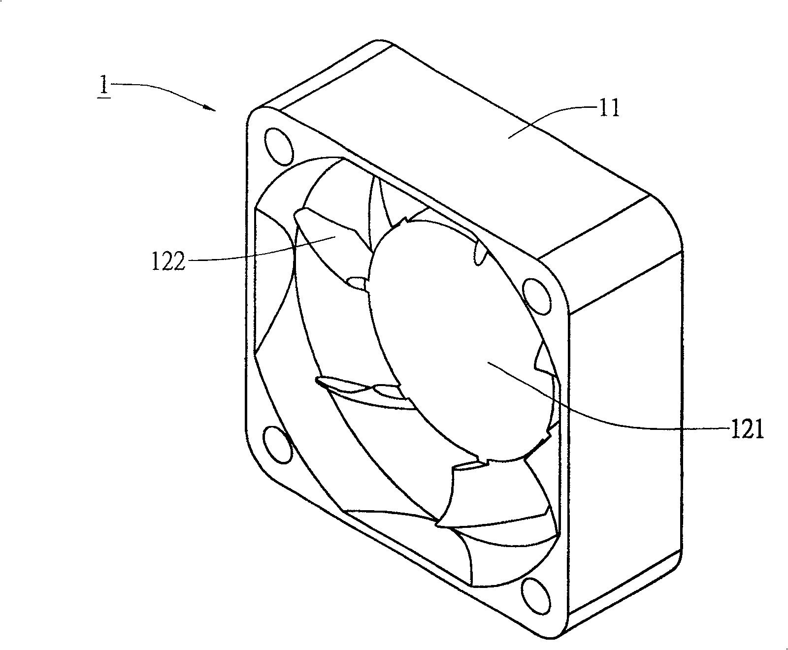
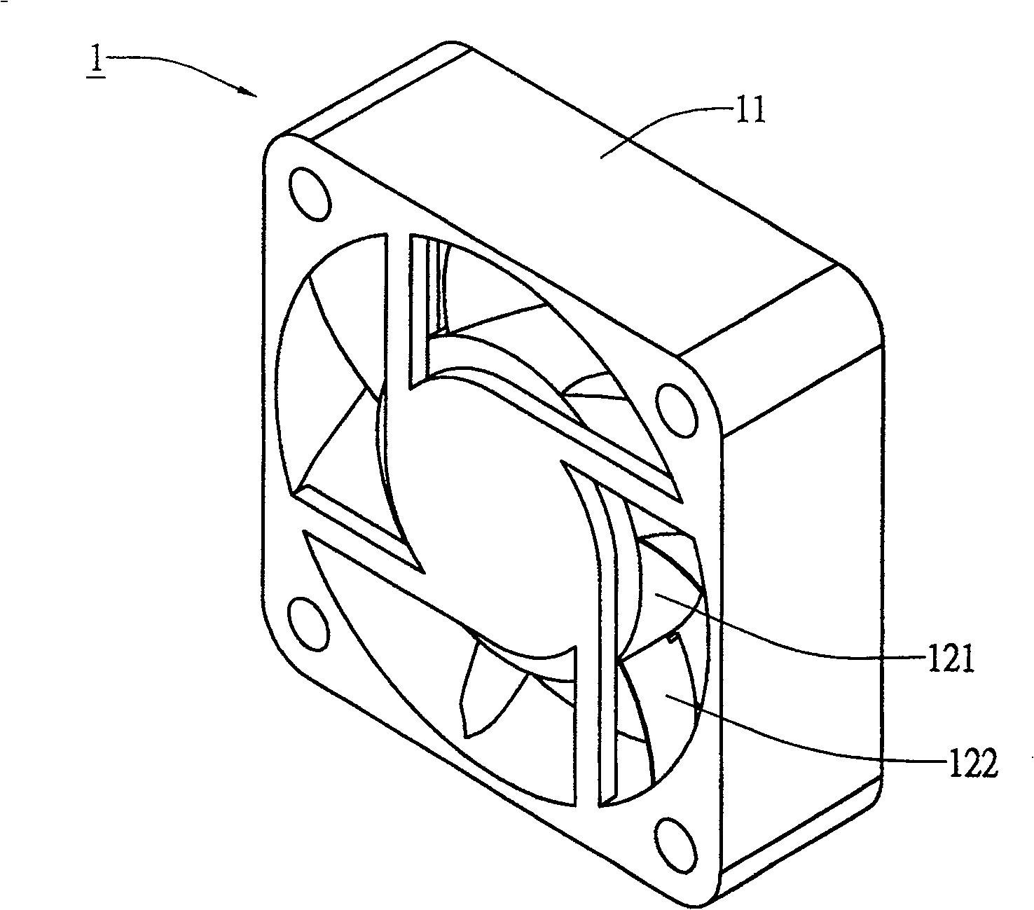
[0003] see Figure 1 to Figure 4 The conventional heat dissipation fan 1 is shown, the heat dissipation fan 1 mainly includes a motor stator 11 and a motor rotor 12, wherein the motor stator 11 has a bearing sleeve 111, and a coil 112 is arranged around the bearing sleeve 111, and the motor rotor 12 Fan blades 122 are set around the hub portion 121 on the upper hub portion 121. An axis 121a is set on the hub portion 121, and a magnet 123 is set on the inner edge of the hub portion 121. When the motor rotor 12 is set on the motor stator 11 Afterwards, the motor rotor 12 is driven to run through the interaction of the coil 112 and the magnet 123, please cooperate Figure 5 As shown, when the cooling fan 1 is running, the air flow generated by the fan blades 122 will form an air stagnation area under the hub portion 121 due to the existence of the hub portion 121, so that the air flow cannot be effectively and smoothly circulated, causing the cooling fan 1 The overall heat dissipation effect is greatly compromised

Method used


Image

  • Thermal fan without inverse flow characteristic
  • Thermal fan without inverse flow characteristic
  • Thermal fan without inverse flow characteristic

Examples


Embodiment Construction

[0073] The present invention is a cooling fan without backflow characteristics, please refer to Figure 6 to Figure 9 In the first embodiment of the present invention shown, the cooling fan 2 is composed of a motor stator 21, a frame 22, a motor rotor 23, and fan blades 24; wherein the bearing sleeve 211 of the motor stator 21 is provided with a coil 212, And combined with the air inlet side 221 of the frame 22 by the support structure 222, the motor rotor 23 has a receiving portion 231, and a magnet 232 is assembled, wherein the fan blade 24 is assembled on a central portion 241, the The central portion 241 is rod-shaped, and a fixed portion 25 is formed at one end of the central portion 241 , and the fixed portion 25 can be an axis.

[0074] Connect the fixed part 25 of the fan blade 24 to the receiving part 231 of the motor rotor 23, so that the fan blade 24 is joined to the motor rotor 23, and the motor rotor 23 with the fan blade 24 assembled on the motor The bearing sle...


PUM


Abstract

The invention discloses a cooling fan without backflow characteristics, which mainly includes a motor stator, a frame, a motor rotor and fan blades; wherein the air inlet side of the frame is assembled with the motor stator by a supporting structure, and the motor rotor is placed in the frame And the motor rotor is set on the motor stator; the motor rotor can be fixedly connected with the fan blade and the fan blade is located at the air outlet side of the cooling fan, so as to increase the air flow area of ​​the cooling fan air outlet, and make the lower end of the fan blade There is no stagnant area to increase the heat dissipation area and reduce noise.

Description

technical field [0001] The invention relates to a heat dissipation fan without backflow characteristics, in particular to a heat dissipation fan which can greatly increase the airflow area of ​​the air outlet of the heat dissipation fan, and make no stagnant area under the fan blades, so as to increase the heat dissipation area and reduce noise. . Background technique [0002] With the rapid development of electronic components and the increase of operating clocks, the heat generated by electronic components has also increased significantly. Therefore, how to effectively remove the large amount of heat to make electronic components operate smoothly has always been an important issue in design. [0003] see Figure 1 to Figure 4 The conventional heat dissipation fan 1 is shown, the heat dissipation fan 1 mainly includes a motor stator 11 and a motor rotor 12, wherein the motor stator 11 has a bearing sleeve 111, and a coil 112 is arranged around the bearing sleeve 111, and th...

Claims


Application Information

Patent Timeline
IPC IPC(8): F04D29/32F04D29/54
Inventor 刘文豪
Owner ASIA VITAL COMPONENTS SHENZHEN CO LTD
Learn More