
Fan of heat sink

Inactive Publication Date: 2007-11-01
ASIA VITAL COMPONENTS SHENZHEN CO LTD
View PDF17 Cites 3 Cited by
  • Summary
  • Abstract
  • Description
  • Claims
  • Application Information

AI Technical Summary

Benefits of technology

[0016] According to an embodiment of the present invention, the first blades and the second blades are adopted for increasing the air flow area in order to increase the air circulation, and the slope of the guiding ring is adopted for smoothly guiding the air between the first and second blades in order to reduce the air disturbance or resistance and thereby promote the heat dissipation effect.

Problems solved by technology

However, operation of the high speed operating semiconductor device generates large amount of heat, which may significantly increase the temperature and may cause abnormal operation of the semiconductor device and also reduce the service life of the semiconductor device if the heat is not timely dissipated.

Method used


Image

  • Fan of heat sink
  • Fan of heat sink
  • Fan of heat sink

Examples


Embodiment Construction

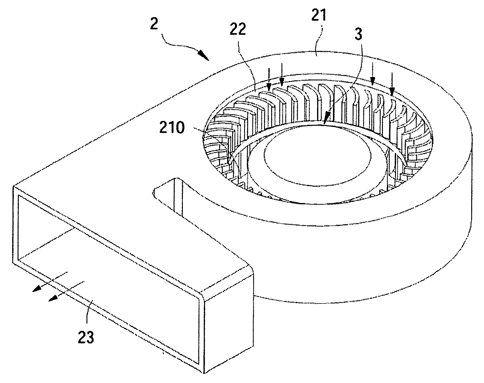
[0027] Referring to FIGS. 4 and 5, the fan according to the preferred embodiment of the present invention is disposed in a housing 2. The housing 2 comprises a circular sidewall 21 enclosing a space 210, an air inlet 22 formed on a top side of the round sidewall 21, wherein the air inlet 22 communicates with the space 210, and an air outlet 23 formed on a side of the housing 2, wherein the air outlet 23 communicates with the space 210. The fan of the heat sink comprises a hub 3, a plurality of ribs 4 and a set of blades 5.

[0028] Referring to FIGS. 6 and 7, the hub 3 comprises a circular sidewall 31. The ribs 4 are disposed around the periphery of the hub 3 and the distal end of the ribs 4 is connected to the circular sidewall 31. In this embodiment, the top surface and the side of the ribs 4 have an arch-shape.

[0029] The fan 5 is connected to the primal end of the ribs 4, and has an outer ring surrounding the bottom flange of the circular sidewall 31 of the hub 3. A plurality of f...


PUM


Abstract

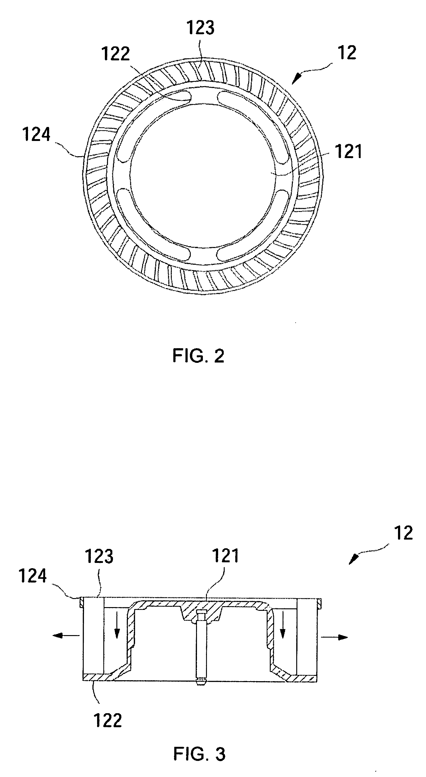
A fan of a heat sink comprising a hub, a plurality of ribs and a set of blades is provided. A distal end of the ribs is connected to circular sidewall of the hub and the set of blades are connected to the primal end of the ribs. The set of blades comprises an outer ring, multiple first blades, a guiding ring connected to the inner side of the first blades and multiple second blades positioned at the inner side of the first blades extending upwards from the top side of the guiding ring. The primal end of the ribs is connected to the guiding ring having an inclined slope extending from the hub towards the outer ring. The first and the second blades are adopted for increasing the air flow area, and thereby increase the air volume and air pressure and the inclined slope of the guiding ring is adopted to smoothly change the flow direction of the sucked air and thereby reduce the resistance to the air flow.

Description

BACKGROUND OF THE INVENTION [0001] 1. Field of Invention [0002] The present invention relates to a fan, and more particularly to a fan of a heat sink. [0003] 2. Description of the Related Art [0004] The rapid development of electronic technology has improved the operation speed of the semiconductor devices, such as central processing unit (CPU) or chip. However, operation of the high speed operating semiconductor device generates large amount of heat, which may significantly increase the temperature and may cause abnormal operation of the semiconductor device and also reduce the service life of the semiconductor device if the heat is not timely dissipated. [0005] Accordingly, it is important to dissipate the heat generated by the operation of the semiconductor device for proper operation thereof. Generally, there are two types of heat sinks, namely air cooler and water cooler. The air cooler including a fan is generally employed in electronic devices for dissipating the heat generat...

Claims


Application Information

Patent Timeline
IPC IPC(8): F04D29/44
CPCF04D25/0613F04D29/584H01L23/467H01L2924/0002H01L2924/00F04D29/281F04D17/16
Inventor LIU, HUNG-SHENGCAO, YA-YU
Owner ASIA VITAL COMPONENTS SHENZHEN CO LTD
Learn More