
Unmanned aerial vehicles

a technology for unmanned aerial vehicles and vehicles, applied in the direction of vehicle position/course/altitude control, process and machine control, instruments, etc., can solve the problems of increasing the number of moving parts in the uav, reducing the risk of damage to the rotors from such foreign objects, and avoiding the effect of affecting the flight

Active Publication Date: 2018-07-12
AIRBUS DEFENCE & SPACE
View PDF4 Cites 26 Cited by
  • Summary
  • Abstract
  • Description
  • Claims
  • Application Information

AI Technical Summary

Benefits of technology

The invention describes a UAV (unmanned aerial vehicle) that can be flown in any direction without losing lift or maneuverability. The arrangement of the rotors allows for full rotation in all directions, allowing the on-board sensors to fully view and map their surroundings. Another aspect of the invention is the design of the main body, which creates a space within the body to facilitate airflow for each rotor.

Problems solved by technology

Unmanned aerial vehicles (UAVs) provide a useful means to aerially explore locations that are unsuitable for manned aircraft, for example because the area is considered too unsafe to allow human access, or because the area is in a confined space that is too small to accommodate a manned aircraft.
Sites where search and rescue UAVs are used may be strewn with obstacles, and may often only be accessible through small openings.
A disadvantage of such a design is the difficulty of manoeuvring the UAV in the x or y direction without substantial vertical movement (i.e. in the z direction).
Such an arrangement improves manoeuvrability, but does not completely eliminate the difficulty of achieving horizontal-only movement.
Rotor-based UAVs sometime incorporate moveable wings or other moveable aerodynamic surfaces in order to improve manoeuvrability but incorporating such extra moveable surfaces increased the number of moving parts in the UAV and can add weight / complexity and / or reduce reliability as a result.
Such an arrangement leaves rotors vulnerable to damage if the UAV comes into contact with an obstacle whilst in flight.
Although it is known to enclose rotors in a protective cowling, the power-to-weight ratio of the resulting UAV is diminished.
A disadvantage of that arrangement is the inability of the UAV to scan its entire surrounding, including the space above it.
A further disadvantage of conventional, elongate multi-rotor UAV helicopter designs is their susceptibility to instability in unpredictable and turbulent airflow.
In particular, both coplanar and v-tail quadcopters do not cope well when buffeted with air currents from different directions, and suffer from reduced stability when flying in close proximity to objects such as walls or beams that disturb local air flow.
Furthermore, if a collision with an object unbalances known UAVs, it is typically very difficult for an operator to maintain flight.
If, for example, a collision leads to a conventional UAV landing the wrong way up, take-off is unlikely to be possible, even if the crash did not result in severe damage.
A drawback of traditional, elongate multi-rotor UAV helicopters is that should one or more rotors be damaged or become inoperable during use, continued flight of the unbalanced UAV can be extremely difficult or impossible.
Since UAVs are often deployed in areas not deemed safe for human access, it is unlikely that retrieval of the UAV will be possible, and so the equipment will be lost.

Method used


Image

  • Unmanned aerial vehicles
  • Unmanned aerial vehicles
  • Unmanned aerial vehicles

Examples


first embodiment

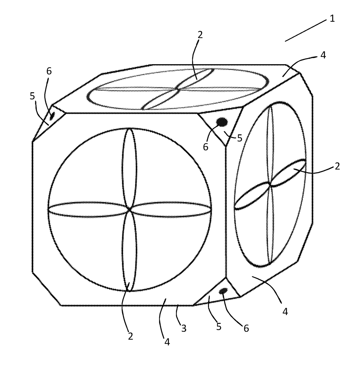
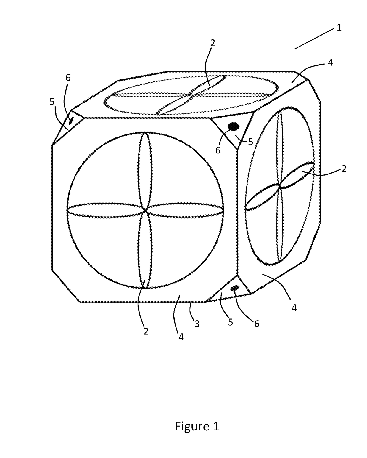
[0095]It will be seen that the UAV 1 of the first embodiment comprises a frame 3 having the shape of a cube with chamfered corners. The frame 3 thus has six eight-sided faces 4 (three of which are hidden from view in FIG. 1) and eight smaller three-sided faces 5 (five of which are hidden from view in FIG. 1) at the corners of the notional cube.

[0096]For the plane of each of the eight-sided faces 4 of the frame 3 of the UAV 1 there is a respective rotor 2 such that the plane of the face is parallel with the plane of rotation of the rotor. Each rotor 2 is recessed into the surface of the frame, thereby protecting the rotor.

[0097]The rotors 2 are in the form of helicopter style rotors. The rotors 2 are each powered by an independent motor (a brushless motor, not shown) controlled using a MOSFET based controller (not shown). The rotors are connected to and driven by the motors using a circumferential drive mechanism (not shown). The drive mechanism may be arranged to drive the rotor via...

second embodiment

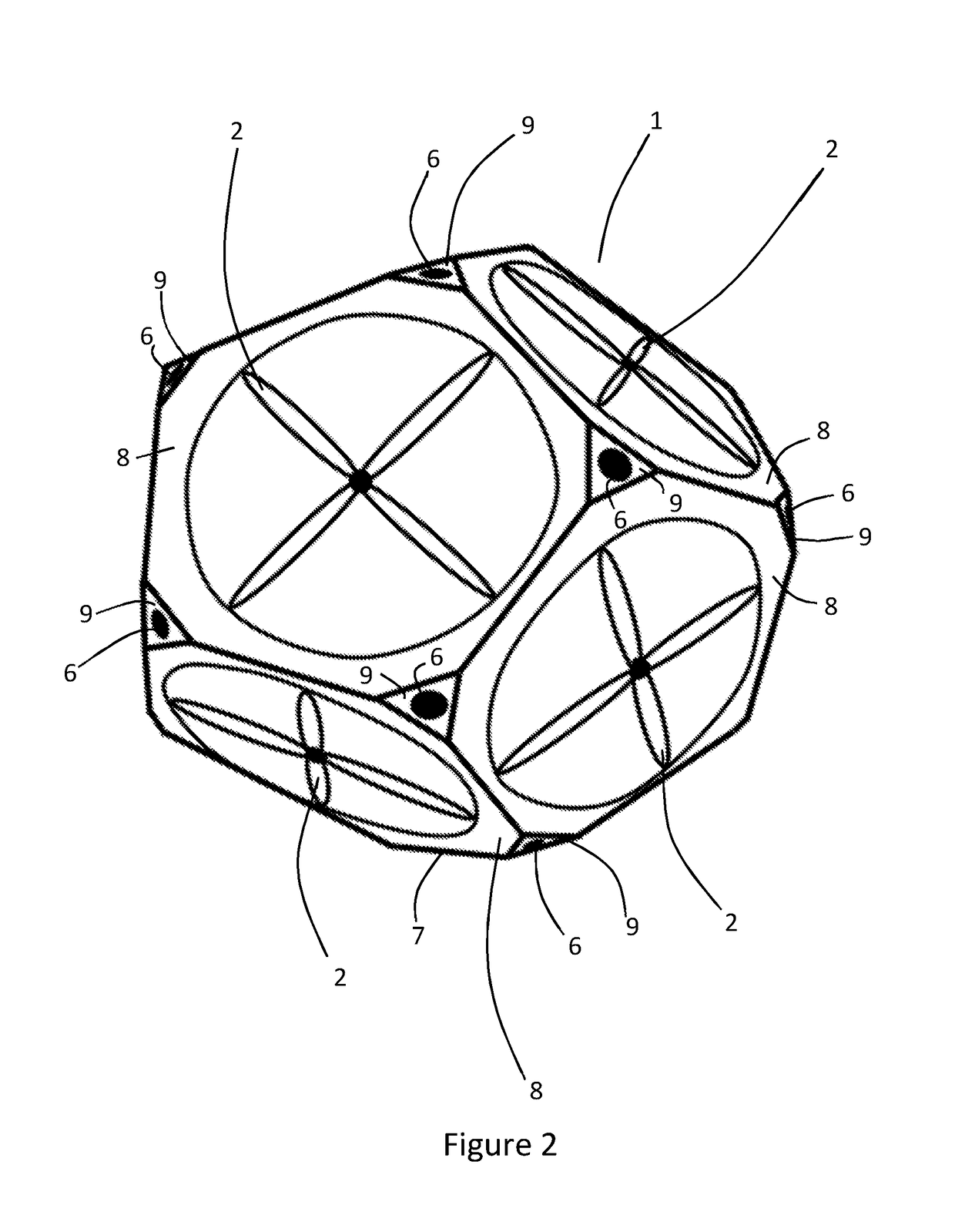
[0111]The body of the UAV 1 of the second embodiment is defined by a shell 7 having the shape of a dodecahedron with chamfered corners. The shell 7 has twelve ten-sided faces 8 (eight of which are hidden from view in FIG. 2) and twenty smaller three-sided faces 9 (thirteen of which are hidden from view in FIG. 2)—at the chamfered corners.

[0112]The plane of each of the ten-sided faces 8 of the shell 7 of the UAV 1 is parallel with the plane of rotation of one of the rotors 2. Each rotor 2 is recessed into the surface of the shell, thereby protecting the rotor.

[0113]The rotors 2 are each powered by an independent motor controlled using a MOSFET based controller (not shown). The rotors are connected to and driven by the motors using a circumferential drive mechanism (not shown).

[0114]The UAV 1 is equipped with twenty camera sensors 6 (seven of which are visible in FIG. 2), each one mounted on a three-sided face 9 of the shell 7. In other words, a camera is mounted on each chamfered cor...

third embodiment

[0116]The UAV 1 of the third embodiment also comprises a shell 10 having the shape of an icosahedron with chamfered corners. The shell 10 has twenty six-sided faces 11 (twelve of which are hidden from view in FIG. 3) and twelve five-sided faces 12 (seven of which are hidden from view in FIG. 3).

[0117]The plane of each of the six-sided faces 11 of the shell 10 of the UAV 1 is parallel with the plane of rotation of one of the rotors 2. Each rotor 2 is recessed into the surface of the shell, thereby protecting the rotor.

[0118]The rotors 2 are each powered by an independent motor controlled using a MOSFET based controller (not shown). The rotors are connected to and driven by the motors using a circumferential drive mechanism (not shown).

[0119]The UAV 1 is equipped with twelve camera sensors 6 (five of which are visible in FIG. 3), each one mounted on a five-sided face 12 of the shell 10. In other words, a camera is mounted on each chamfered corner of the icosahedron-shaped UAV 1.

[0120]...


PUM


Abstract

Unmanned aerial vehicles (1), and methods of flying such, comprising at least four rotors (2) arranged such that the plane of rotation of each rotor (2) is co-planar with a face of a notional polyhedron, and wherein each face of the notional polyhedron is co-planar with the plane of rotation of at least one rotor (2). Such methods comprise: a first step of flying the vehicle (1) using a first rotor set (2a-c) to provide lift; and, a second step using a second rotor set (2d-f) to provide lift; wherein, the second rotor set (2d-f) includes at least one rotor (2) that is not used to provide lift in the first step or that operates so that airflow through the rotor (2) is in the opposite direction to that through the rotor (2) during the first step; and, wherein at least one of the first and second sets (2a-c, 2d-f) comprises a plurality of rotors (2).

Description

FIELD OF THE INVENTION[0001]The present invention concerns improvements in and relating to unmanned aerial vehicles. More particularly, but not exclusively, this invention concerns an unmanned aerial vehicle comprising at least four rotors, each rotor having a plane of rotation, wherein the at least four rotors are arranged such that the plane of rotation of each rotor is co-planar with a face of a notional polyhedron, and wherein each face of the notional polyhedron is co-planar with the plane of rotation of at least one rotor.[0002]The invention also concerns improved methods of flying unmanned aerial vehicles. More particularly, but not exclusively, this invention concerns a method of flying an unmanned aerial vehicle, the vehicle comprising at least four independently controllable rotors, wherein the method comprises: a first step of flying the vehicle using a first set of the rotors to provide lift; and a second step of flying the vehicle using a second set of the rotors to pro...

Claims


Application Information

Patent Timeline
IPC IPC(8): B64C39/02
CPCB64C39/024B64C39/028B64C2201/027B64C2201/108B64C2201/127B64C2201/162B64U10/13B64U30/20B64U50/14B64U2101/30B64U30/26B64C27/24G05D1/0094G05D1/102
Inventor HASINSKI, JULIANTURTON, BRIAN
Owner AIRBUS DEFENCE & SPACE
Learn More