Heat-dissipating device and a housing thereof

a heat dissipating device and heat dissipating technology, which is applied in the direction of positive displacement liquid engines, piston pumps, liquid fuel engines, etc., can solve the problems of reducing the efficiency of heat dissipation, so as to improve the heat dissipation efficiency and increase the dimension. , the effect of airflow ra

Inactive Publication Date: 2006-12-21
DELTA ELECTRONICS INC
View PDF16 Cites 1 Cited by
  • Summary
  • Abstract
  • Description
  • Claims
  • Application Information

AI Technical Summary

Benefits of technology

[0009] Another object of the invention is to provide a heat-dissipating device and a housing thereof, wherein an inner wall of the housing extends outwards to enlarge its intake airflow area so that the impeller of the heat-dissipating device may increase its dimension with the outward extension of the housing. Thus, the airflow rate may be increased and the heat-dissipating efficiency may be enhanced.
[0010] Still another object of the invention is to provide a heat-dissipating fan and a housing thereof, wherein the air passage formed by the inner wall of the passage of the housing reduces gradually and evenly in its cross-sectional area. Thus, the air streams produced by the rotation of blades of the impeller of the heat-dissipating device can be effectively concentrated to the center and then blow to the center portion of the heat sink having the highest temperature when the heat sink is assembled with the heat-dissipating device so as to enhance its heat-dissipating efficiency.

Problems solved by technology

However, since the electrical element (such as a central processing unit (CPU) or circuit board) raises its temperature during operation, the element tends to be consumed and the lifetime thereof tends to be shortened if the element is continuously kept at the high-temperature condition.
The optimized design in the shape of the blade based on the curve of the air passage is also restricted, and the space and material of the fan housing are also wasted.
Besides, due to the restriction in the construction of the fan housing, air may be taken into the fan only in the axial direction.
However, it only can achieve very limited improvement effect in the increased intake airflow rate by doing so.

Method used


Image

  • Heat-dissipating device and a housing thereof
  • Heat-dissipating device and a housing thereof
  • Heat-dissipating device and a housing thereof

Examples


Embodiment Construction

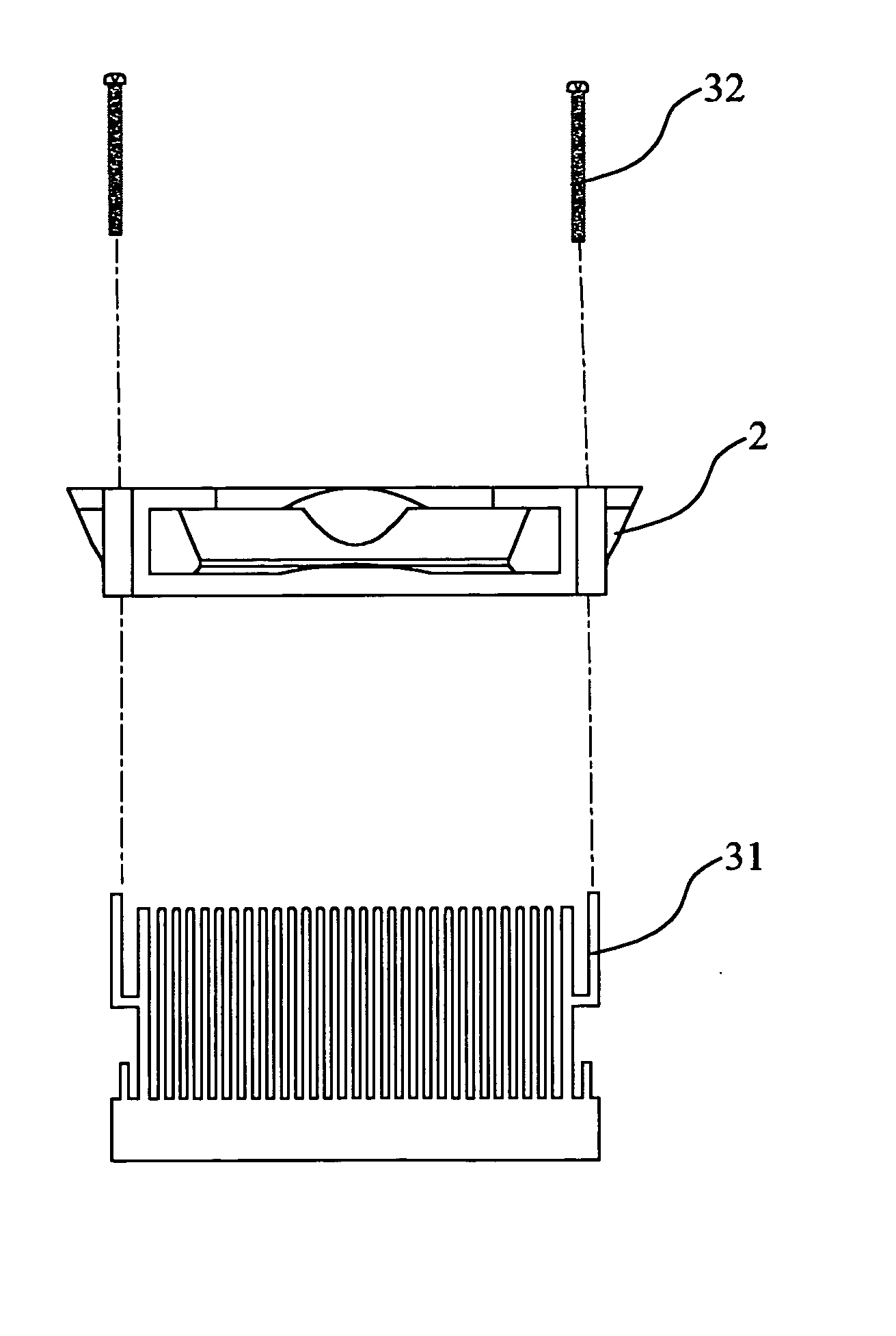
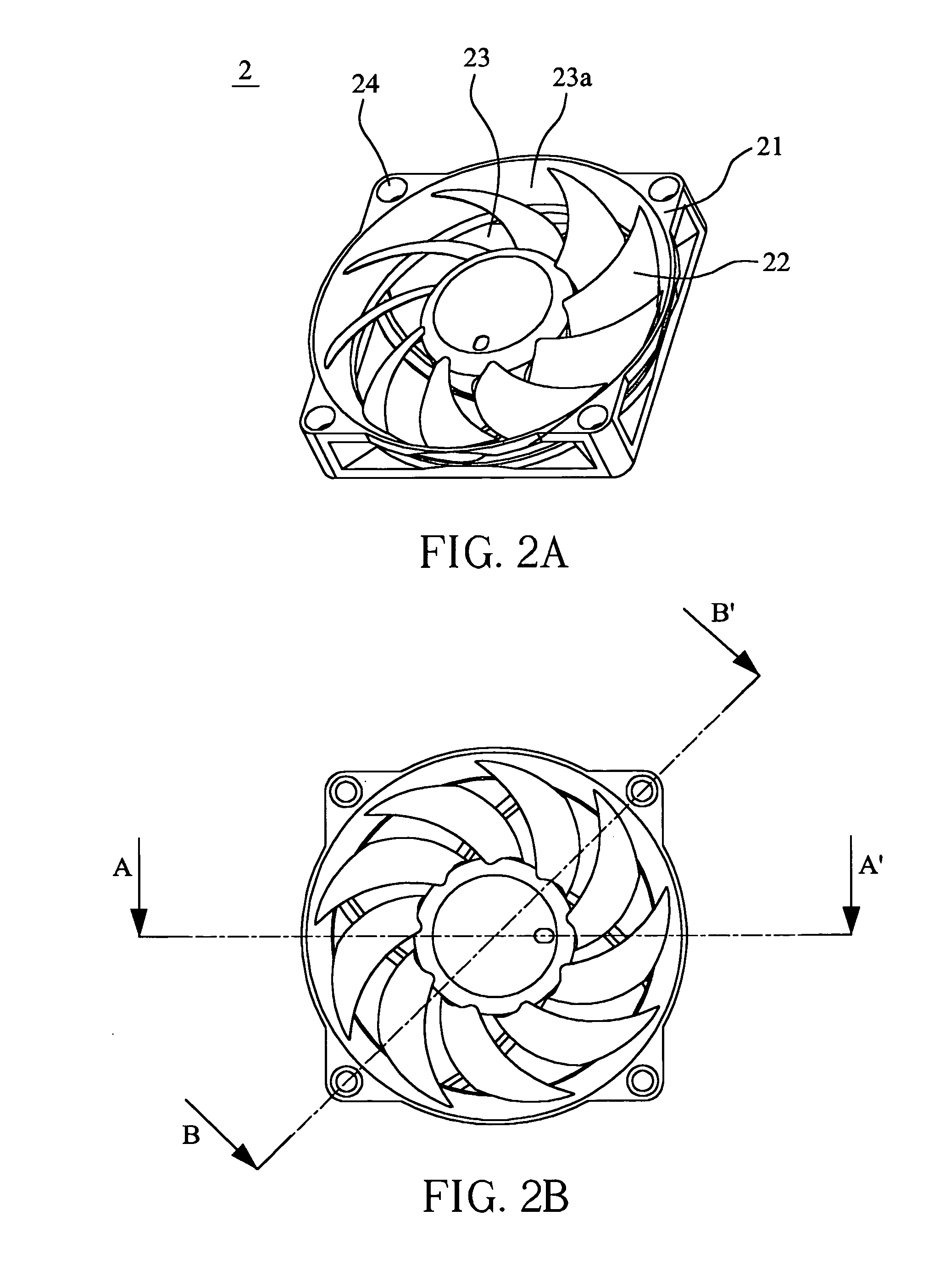
[0040] Referring to FIGS. 2A to 2D, which show a heat-dissipating device according to a first preferred embodiment of the invention. The heat-dissipating device 2 is mainly composed of a housing and an impeller 22. The housing includes a rectangular outer frame 21 having an air inlet, an air outlet, and a passage 23 connecting the air inlet to the air outlet. An inner wall 23a of the passage extends radially outwards with respect to a rotational axis of the fan motor of the heat-dissipating device or an axis of passage, or even protrudes over the rectangular outer frame 21. Since the air inlet side of the housing has a circular shape extending outwards, the bottom part of the housing is still kept as a rectangular shape, and screw holes 24 and their positions are kept unchanged, the way of assembling the housing with other elements is also kept unchanged. The dimension of the blade of the impeller can be enlarged along with the outward extension of the inner wall of the housing, and...


PUM


Abstract

A heat-dissipating device and a housing thereof. The housing includes a passage for guiding an air stream flowing from an opening to another opening, wherein an inner wall of the passage at at least one of the opening sides extends radially outwards with a rotational axis of the heat-dissipating device or the passage so as to enlarge intake or discharge area for the air streams. Accordingly, the intake airflow rate may be greatly increased and the heat-dissipating efficiency of the heat-dissipating device may be greatly enhanced without changing assembling conditions with other elements.

Description

CLAIM OF PRIORITY TO RELATED APPLICATION [0001] This application is a divisional patent application, which claims priority under 35 U.S.C. § 120 of U.S. Patent Application No. 10 / 626,267, filed on Jul. 23, 2003, and which is incorporated by reference herein.BACKGROUND OF THE INVENTION [0002] 1. Field of the invention [0003] The invention relates to a heat-dissipating device and a housing thereof, and more particularly to an axial fan having an increased intake airflow rate without modifying the assembling conditions with other elements so as to greatly enhance the heat-dissipating performance of the fan, and a housing for the fan. [0004] 2. Description of the Related Art [0005] A typical electrical product usually includes electrical elements positioned in a closed housing in order to prevent the electrical elements from being contaminated with particles in the air. However, since the electrical element (such as a central processing unit (CPU) or circuit board) raises its temperatur...

Claims


Application Information

Patent Timeline
Patent Type & Authority Applications(United States)
IPC IPC(8): H05K7/20F04D29/54F04D25/08F04D29/58H01L23/467
CPCF04D29/545F04D29/582H01L23/467H05K7/20172H01L2924/0002H01L2924/00
Inventor KO, HAO-WENLEI, TSUNG-YULIN, KUO-CHENGCHANG, HSIOU-CHEN
Owner DELTA ELECTRONICS INC
Why Eureka
Try Eureka