Tissue penetrating catheters having integral imaging transducers and their methods of use

a tissue penetrating catheter and imaging transducer technology, applied in the field of medical devices and methods, can solve the problems of cardiac disease, a major cause of premature death and morbidity, and achieve the effect of reducing the profile and facilitating accurate and reliable orientation of tissue penetrating catheters

Inactive Publication Date: 2009-12-29
MEDTRONIC VASCULAR INC
View PDF19 Cites 61 Cited by
  • Summary
  • Abstract
  • Description
  • Claims
  • Application Information

AI Technical Summary

Benefits of technology

[0006]This invention facilitates accurate and reliable orientation of a tissue penetrating catheter in a blood vessel so that an adjacently located blood vessel or other anatomical target can be accurately penetrated, while eliminating the need for formation of a separate imaging lumen within the tissue penetrating catheter. Thus, because the need for an imaging lumen has been eliminated, the tissue penetrating catheters of this invention may be of reduced profile (e.g., 5-7 French diameter).
[0007]In accordance with the invention, there is provided a tissue penetrating catheter device that comprises an elongated catheter having an instrument lumen to facilitate the passage of a tissue penetrator, a penetrator direction marker, and an integral imaging transducer (e.g., an IVUS transducer). To facilitate orientation, the imaging transducer is useable to provide an imaging signal from which an image of the target structure and other adjacent anatomical structures can be obtained. The imaging transducer is fixedly mounted on or within the catheter, thereby eliminating the need for a separate imaging lumen which requires sufficient clearance in the lumen to allow a separate imaging transducer to be advanced and retracted in the lumen. This in turn enables the catheter to be of smaller cross sectional area. In addition, by fixedly mounting the imaging transducer on the catheter, its orientation relative to the catheter and certain components on the catheter can be specifically known.
[0012]The imaging transducer of the current invention is preferably an ultrasound imaging transducer and more preferably a phased array transducer. Because the phased array transducer can be fixed in a permanent manner on or within the catheter body, said phased array transducer has the advantage of being useable with or with out an imageable marker to obtain reliable and accurate orientation. Moreover, the nature of the imaging elements and the fact the imaging signal can be transmitted by multiplexing numerous signals on fewer lead wires contribute to the small profile of the catheter.

Problems solved by technology

Atherosclerotic cardiovascular disease remains a major cause of premature death and morbidity, in most regions of the world.

Method used


Image

  • Tissue penetrating catheters having integral imaging transducers and their methods of use
  • Tissue penetrating catheters having integral imaging transducers and their methods of use
  • Tissue penetrating catheters having integral imaging transducers and their methods of use

Examples


first embodiment

A. Catheter With Phased Array (or Rotatable) Imaging Transducer and Mark r Structure For Indicating Penetrator Path

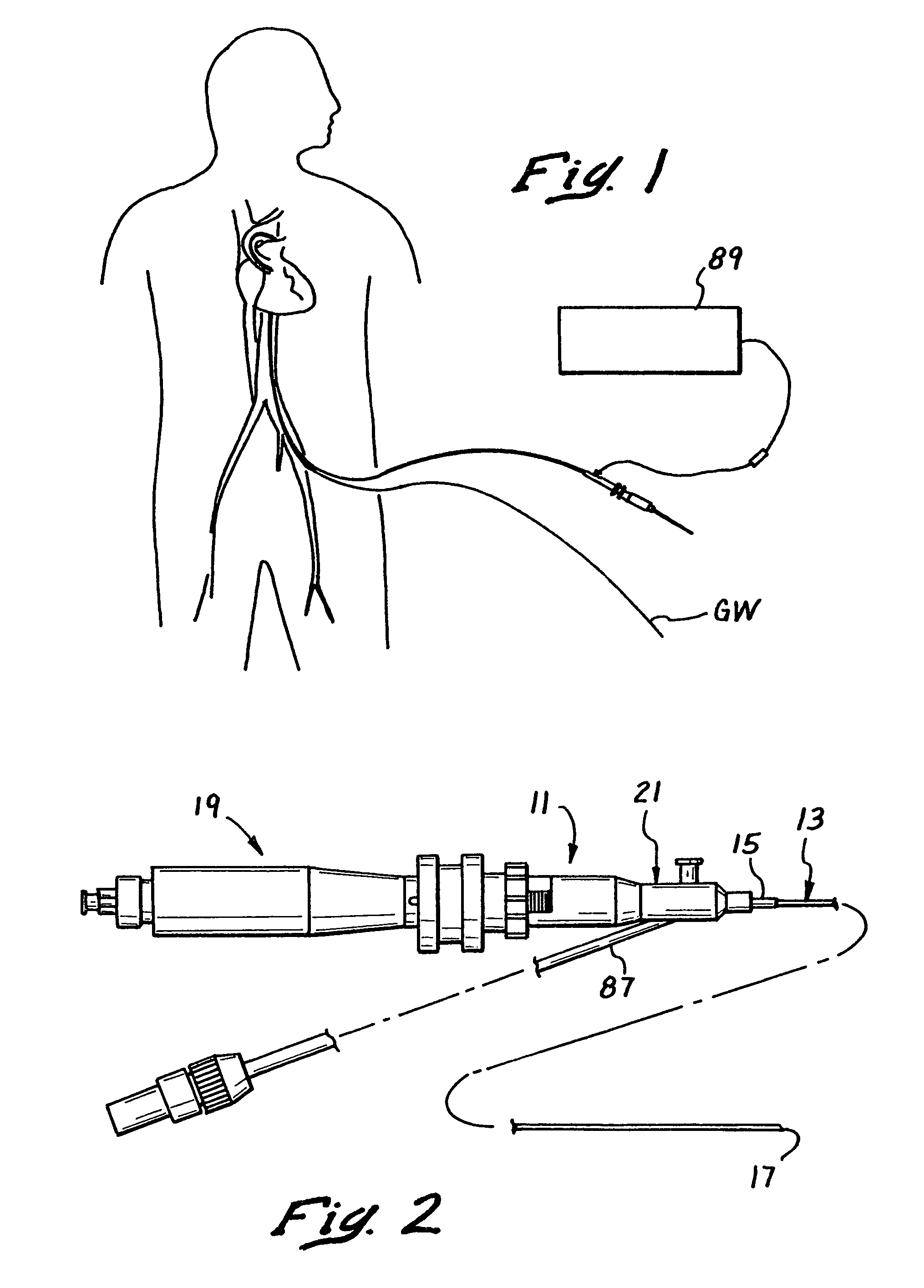
[0040]FIG. 2 shows a catheter 11 constructed in accordance with the teachings of this invention, while FIG. 1 shows the catheter 11 in use on a human patient. In the embodiment illustrated, the catheter 11 includes an elongated catheter body 13 having a proximal end 15, a distal end 17, a handle 19 and a hub 21 coupled to the proximal end of the catheter body 15 and to the handle. The handle 19 may also serve as a controller for use in advancing and retracting the penetrating instrument, such as a tissue penetrator 85 described more fully below.

The Catheter Body

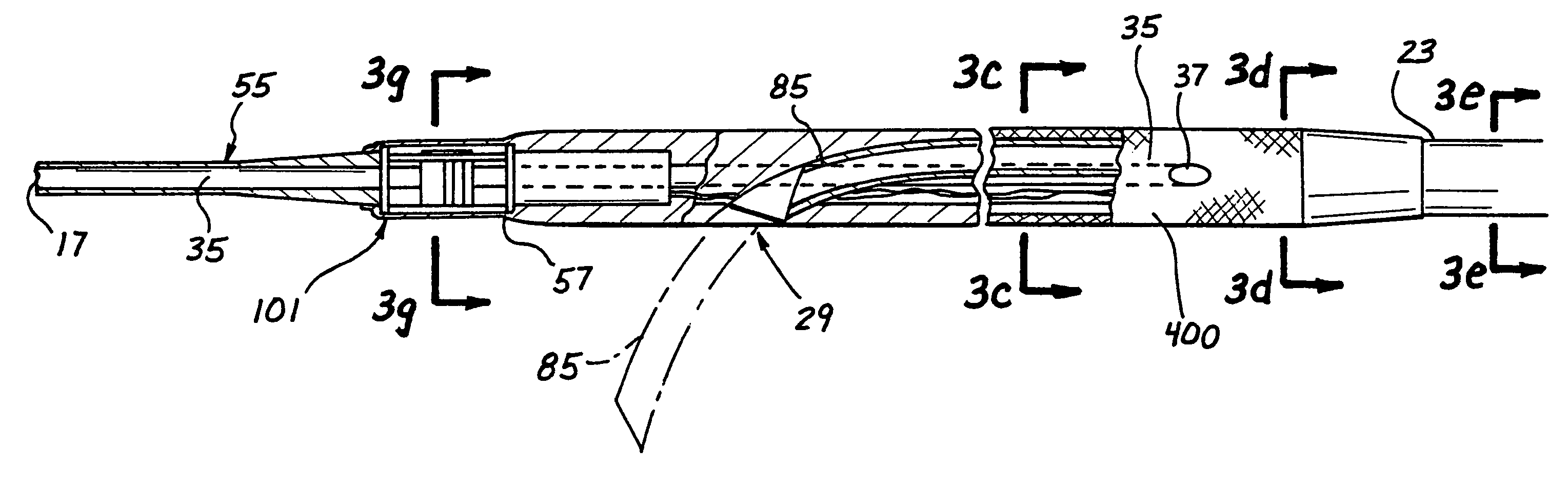
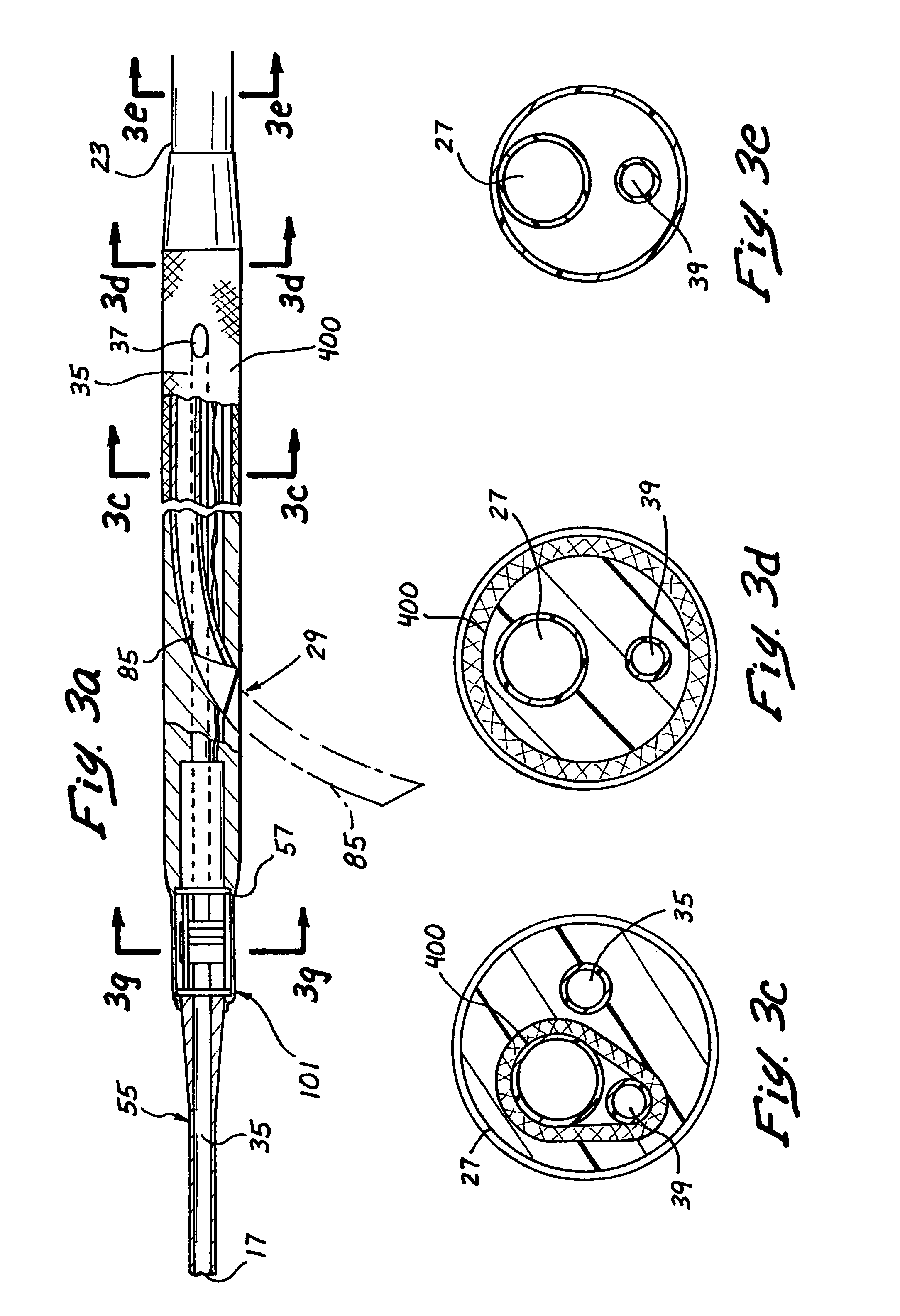
[0041]The catheter body 13 includes a relatively rigid proximal section 23 shown in FIGS. 2 and 3a which may be constructed, for example, of a metal hypo tube and an elongated flexible distal section or region 25 suitably joined to the proximal section. A hand piece 19 is attached to the proximal end of the prox...

second embodiment

B. Catheter with Fixedly Mounted Imaging Transducer Useable Without Marker Structure

[0051]FIG. 4 shows a second embodiment of the catheter 11a which is identical to the catheter 11 in all respects not shown or specified as being different herebelow. Portions of the catheter 11a corresponding to portions of the catheter 11 are designated by corresponding reference numerals followed by the letter a.

[0052]The primary difference between the catheters 11 and 11a is that the catheter 11a has no imageable marker structure 101. Instead, its imaging transducer 81a is mounted in a fixed position such that one particular element 121pp (or a group of particular elements) is / are designated as the penetrator path but rather is mounted in a fixed orientation within or upon the catheter such that a selected one (or selected ones) of the individual imaging elements 121 (e.g., crystals) of the phased array is positioned in known special relation to the path or plane of the path that will be followed...


PUM

PropertyMeasurementUnit
lengthaaaaaaaaaa
lengthaaaaaaaaaa
distanceaaaaaaaaaa

Abstract

A catheter device that is useable to penetrate from a blood vessel in which the catheter device is positioned to a target location comprises a flexible catheter advanceable into the first blood vessel, a tissue penetrator lumen adapted to receive an operative tissue penetrator which is usable to penetrate from the blood vessel to the target location when properly aimed. Further said catheter including an imaging transducer fixedly mounted on or within the catheter body to provide an imaging signal from which an image of the target location can be obtained. The catheter device may include an imageable marker on the catheter to form on the image obtainable from the imaging signal a penetrator path indication that indicates the path that will be followed by the tissue penetrator when the tissue penetrator exits from the catheter. Alternatively, or addition thereto, the imaging transducer may comprise a plurality of imaging elements which are located so that the penetrator path indication can be obtained. A method of utilizing such a catheter device to bypass an arterial obstruction is also disclosed.

Description

RELATED APPLICATIONS[0001]This is a continuation of U.S. patent application Ser. No. 10 / 033,836 filed on Dec. 26, 2001 now U.S. Pat. No. 6,660,024, which is a continuation of U.S. patent application Ser. No. 09 / 282,774 filed on Mar. 31, 1999, now issued as U.S. Pat. Ser. No. 6,375,615, which claims priority to U.S. Provisional Application No. 60 / 080,196, filed Mar. 31, 1998 and is a continuation-in-part of U.S. patent application Ser. No. 08 / 837,294, filed on Apr. 11, 1997, now issued as U.S. Pat. Ser. No. 6,302,875, which itself is a continuation-in-part of two-earlier filed applications, namely; U.S. patent application Ser. No. 08 / 730,327 filed Oct. 11, 1996, now issued as U.S. Pat. Nos. 6,190,353 and 08 / 730,496, filed Oct. 11, 1996, now issued as U.S. Pat. No. 5,830,222, and both of which claim priority to earlier-filed U.S. Provisional Patent Application Nos. 60 / 005,164 filed Oct. 13, 1995 and 60 / 010,613 filed Feb. 2, 1996.FIELD OF THE INVENTION[0002]The present invention relate...

Claims


Application Information

Patent Timeline
Patent Type & Authority Patents(United States)
IPC IPC(8): A61B8/00A61B8/14A61M25/098A61B1/313A61B8/12A61B17/00A61B17/064A61B17/11A61B17/12A61B17/22A61B17/30A61B17/34A61B18/00A61B18/14A61B18/24A61B19/00A61F2/00A61F2/02A61F2/90A61K31/195A61M25/00A61M25/01A61M29/00
CPCA61B17/3403A61F2/2493A61F2/95A61K31/195A61B1/3137A61B8/12A61B17/11A61B17/12109A61B17/12172A61B17/3207A61B17/3417A61B18/1445A61B8/445A61B2017/22038A61B2017/22072A61B2017/22077A61B2017/306A61B2017/347A61B2017/3488A61B2018/00392A61B2018/00869A61B2018/1425A61B2019/5276A61B2019/528A61B2019/5425A61B2019/5429A61B2019/5458A61F2/07A61F2/90A61F2002/30079A61F2002/8486A61F2210/009A61M25/0133A61M25/0152A61M29/00A61M29/02A61M2025/0076A61M2025/018A61M2025/1052A61B8/4488A61B17/320725A61B17/3496A61B18/00A61B18/1477A61B18/1492A61B18/24A61B19/38A61B19/5212A61B19/54A61B2017/00243A61B2017/00247A61B2017/00252A61B2017/003A61B2017/00455A61B2017/00504A61B2017/1107A61B2017/1139A61B2017/12127A61B2017/22069A61B90/361A61B2090/3784A61B90/40A61B2090/378A61B90/39A61B2090/3925A61B2090/3929A61B2090/3958
Inventor FLAHERTY, J. CHRISTOPHERWHITT, JASON B.CHANG, JOHN Y.THOLFSEN, DAVID R.EVARD, PHILIP C.MAKOWER, JOSHUA
Owner MEDTRONIC VASCULAR INC
Why Eureka
Try Eureka