Fluid flow diffusers and vibratory separators

a technology of vibratory separator and fluid flow diffuser, which is applied in the direction of filtration separation, moving filter element filter, separation process, etc., can solve the problems of poor performance and operation down time, affecting the ability of the lower deck to move solids to the exit end of the lower deck, and affecting the movement of solids on the lower deck

Inactive Publication Date: 2005-03-22
VARCO I P INC
View PDF19 Cites 68 Cited by
  • Summary
  • Abstract
  • Description
  • Claims
  • Application Information

AI Technical Summary

Benefits of technology

The present invention, in certain aspects, discloses a vibratory separator or shale shaker with flow diffusing apparatus positioned below an exit end of an upper deck in a multi-deck machine and above a lower deck. The flow diffusing apparatus is located to intercept all, a significant part of, or the bulk of fluid flowing down from the upper deck thereby diffusing it to prevent it from impacting on a relatively small area of the lower deck and to spread the flow out over a larger area.

Problems solved by technology

In some circumstances, e.g. at relatively high fluid flow rates, fluid flowing from an upper deck to a lower deck can create a water barrier on the lower deck which impedes the desired movement of solids on the lower deck to an exit end of the lower deck.
Such a fluid flow can also wear out part of the lower deck prematurely, resulting in poor performance and operation down time to fix or replace part of the lower deck.

Method used


Image

  • Fluid flow diffusers and vibratory separators
  • Fluid flow diffusers and vibratory separators
  • Fluid flow diffusers and vibratory separators

Examples


Embodiment Construction

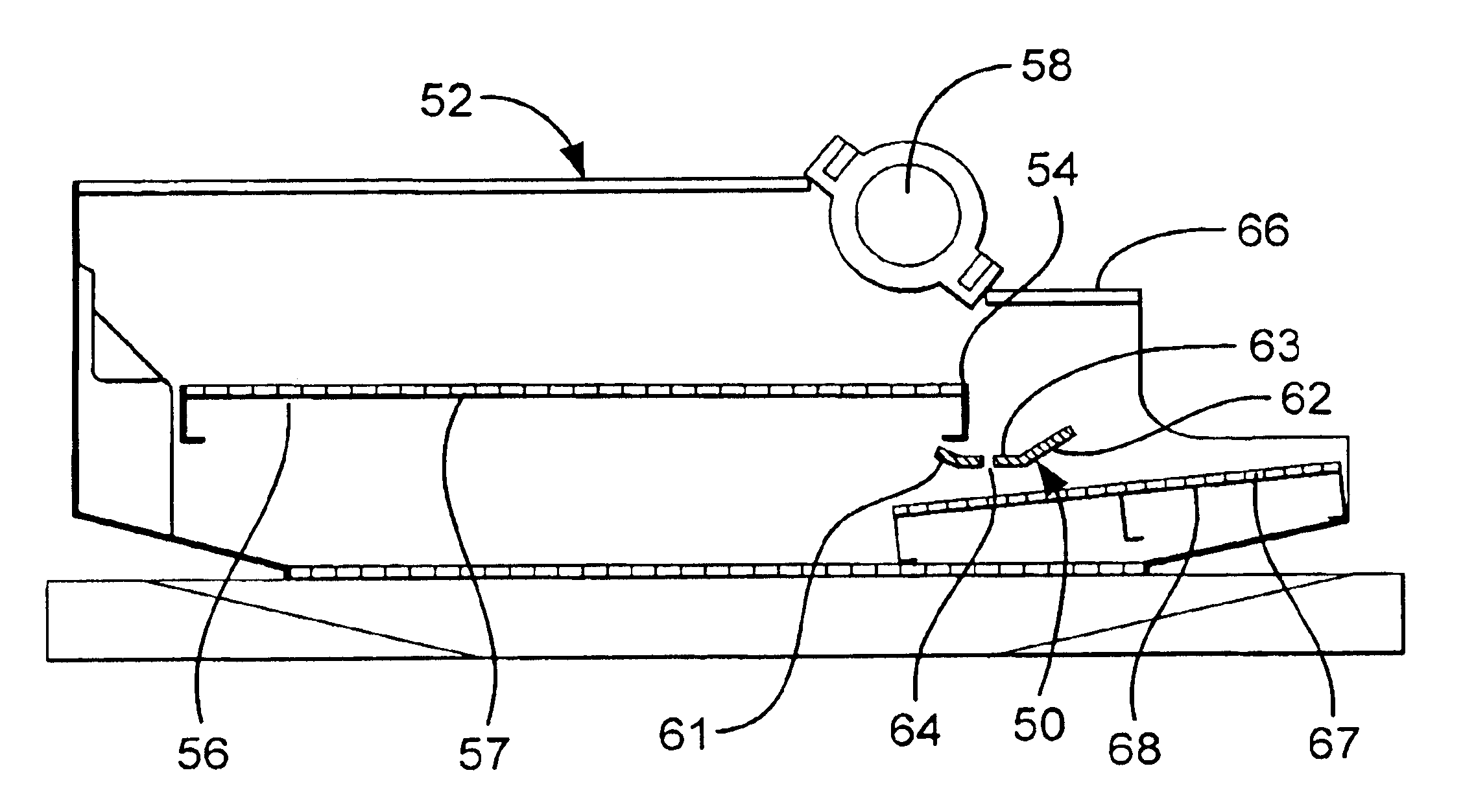
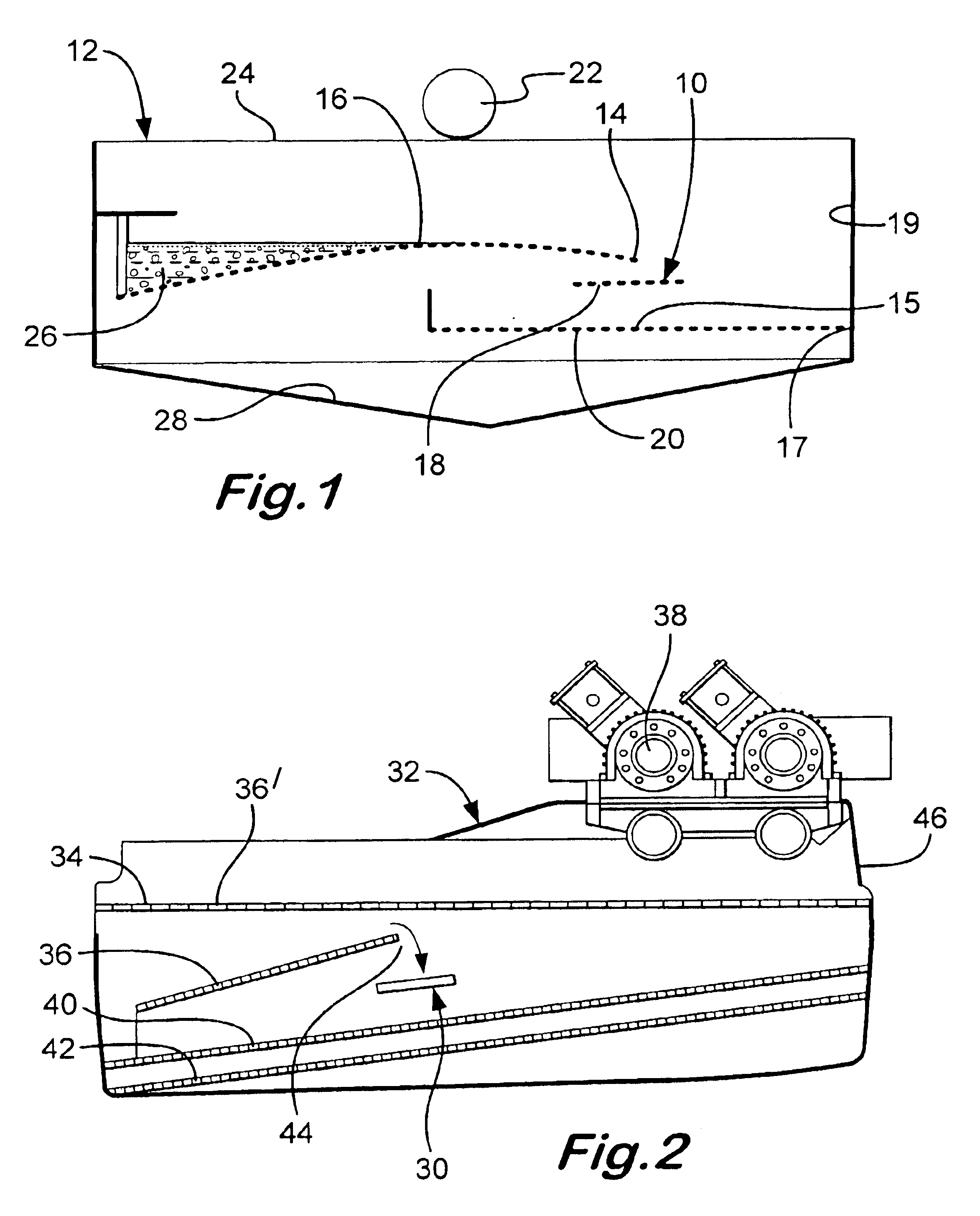
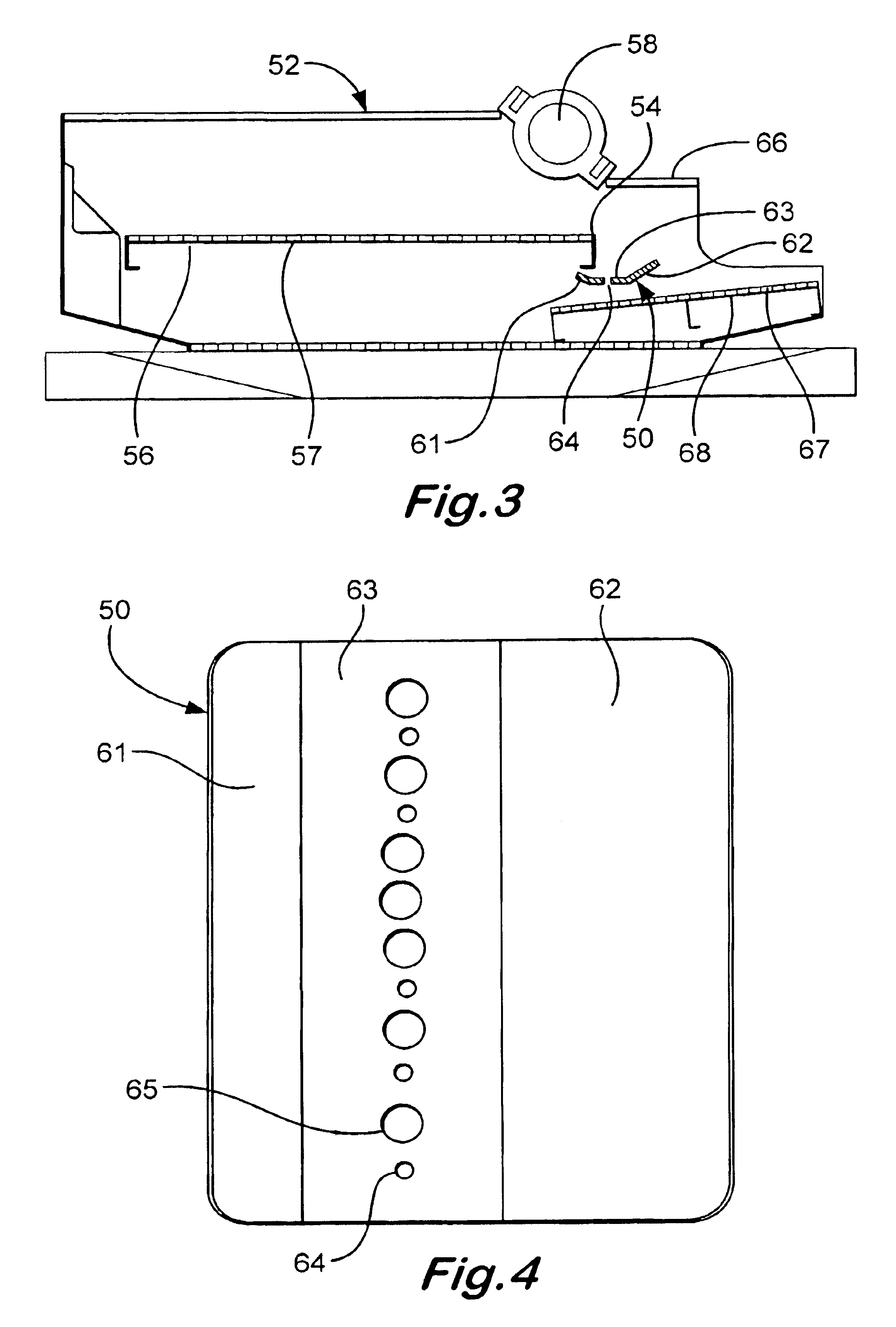
FIG. 1 shows schematically a shale shaker 12 according to the present invention with a flow diffusion apparatus 10 according to the present invention. Fluid flowing from an exit end 12 of an upper screening deck 16 hits the flow diffusion apparatus 10. Without the flow diffusion apparatus 10 in place, the fluid flowing from above would impact an area 15 on a lower screening deck 20. A basket 24 supports the screening decks. The flow diffusion apparatus 10 (as may be the case for any such apparatus according to the present invention) is secured to the basket 24. It is also within the scope of the present invention for the flow diffusion apparatus 10 (as may be any flow diffusion apparatus according to the present invention) to be connected to the upper screen deck, the lower screen deck, or both in addition to, or instead of, securement to the basket 24.

The flow diffusion apparatus 10 (as may any apparatus according to the present invention) has one or a series of holes 18 therethrou...


PUM

PropertyMeasurementUnit
angleaaaaaaaaaa
anglesaaaaaaaaaa
surface areaaaaaaaaaaa

Abstract

A vibratory separator including basket apparatus for holding screening apparatus, at least one upper screen apparatus in the basket, the at least one upper screen apparatus having a fluid exit end, at least one lower screen apparatus in the basket below the at least one upper screen apparatus, fluid flowable from the at least one upper screen apparatus down onto the at least one lower screen apparatus, flow diffusion apparatus mounted below the fluid exit end of the at least one upper screen apparatus and above the at least one lower screen apparatus, so that fluid flowing down from the at least one upper screen apparatus flows onto the flow diffusion apparatus and is diffused thereby, and vibrator apparatus for vibrating the basket and the screen apparatus therein.

Description

BACKGROUND OF THE INVENTION1. Field of the InventionThe present invention is directed to vibratory separators and shale shakers, and, in certain particular aspects, to multi-deck separators and shakers with flow diffusers for diffusing fluid flowing from an upper deck to a lower deck.2. Description of Related ArtVarious prior art vibratory separators and shale shakers have one or more upper screening decks positioned above one or more lower screening decks. Although some fluid flows through the upper deck(s) to the lower deck(s), often upper deck(s) are positioned so that an exit end of the upper deck(s) is above part of a lower deck. In such a situation, fluid can flow directly from an upper deck to a lower deck without passing through screening, screens, or screen assemblies on the upper deck. In some circumstances, e.g. at relatively high fluid flow rates, fluid flowing from an upper deck to a lower deck can create a water barrier on the lower deck which impedes the desired movem...

Claims


Application Information

Patent Timeline
Patent Type & Authority Patents(United States)
IPC IPC(8): B01D33/03B01D33/00B07B1/46
CPCB01D33/0376B07B1/46B01D33/37B01D33/722B07B2230/01
Inventor SEYFFERT, KENNETH W.STRONG, GARY STEVENMCCLUNG, III, GUY L.
Owner VARCO I P INC
Why Eureka
Try Eureka