
Suction holder for razor

a razor and suction holder technology, applied in the direction of washstands, machine supports, other domestic objects, etc., can solve the problem of difficult to remove the razor from the holder

Inactive Publication Date: 2005-03-22
ADAMS MFG
View PDF22 Cites 42 Cited by
  • Summary
  • Abstract
  • Description
  • Claims
  • Application Information

AI Technical Summary

Benefits of technology

I provide a holder for a razor that has a suction cup of the type having a cup-shaped base and a generally cylindrical neck. A bore having a multi-sided, preferably square, cross section passes transversely through the neck. A split ring has spaced apart ends having a same cross section. These ends fit within either end of the bore in the neck of the suction cup. The suction cup is an otherwise conventional suction cup made of a soft vinyl. The

Problems solved by technology

However, when I made such a holder I discovered that the ring did not remain in a plane perpendicular to the wall on which the holder was mounted.
This made it difficult to remove the razor from the holder.

Method used


Image

  • Suction holder for razor
  • Suction holder for razor
  • Suction holder for razor

Examples


Embodiment Construction

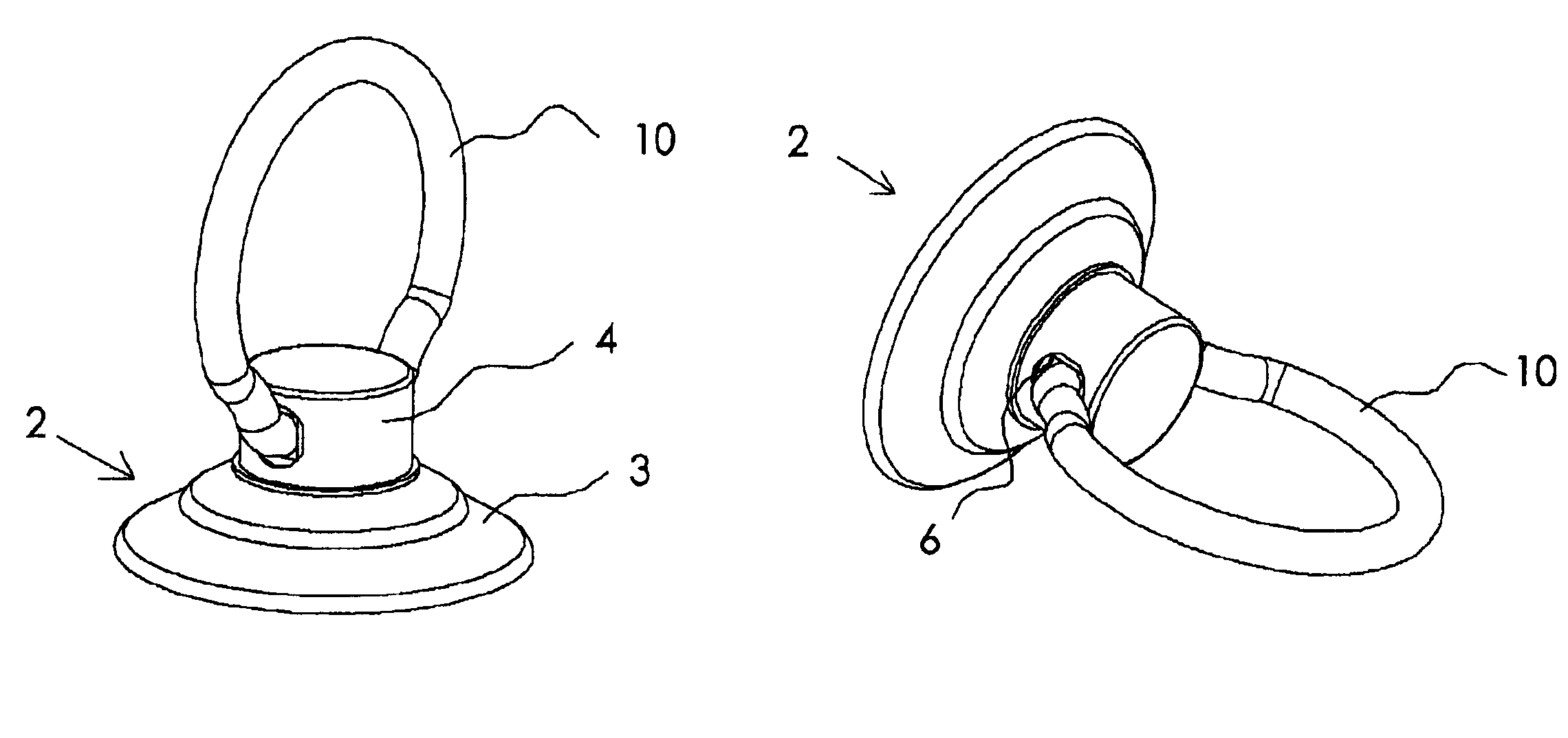
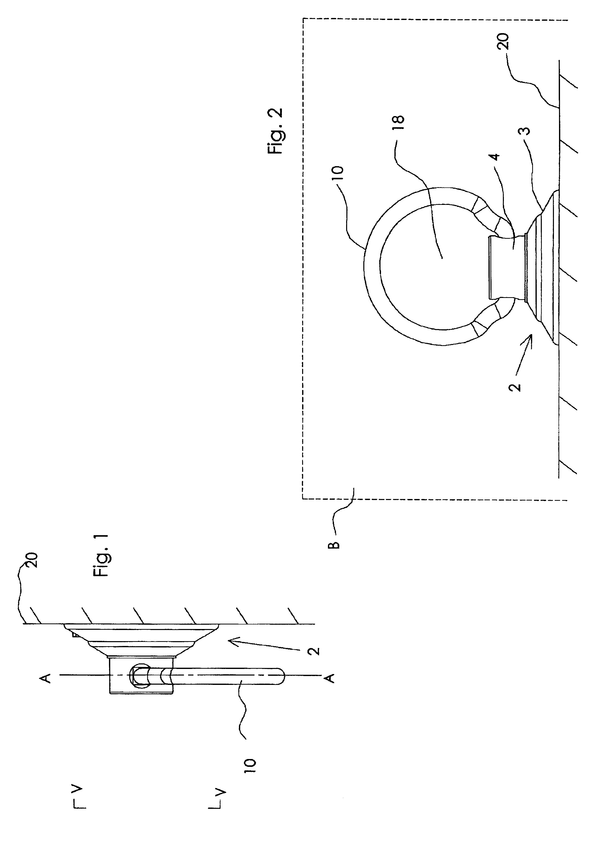
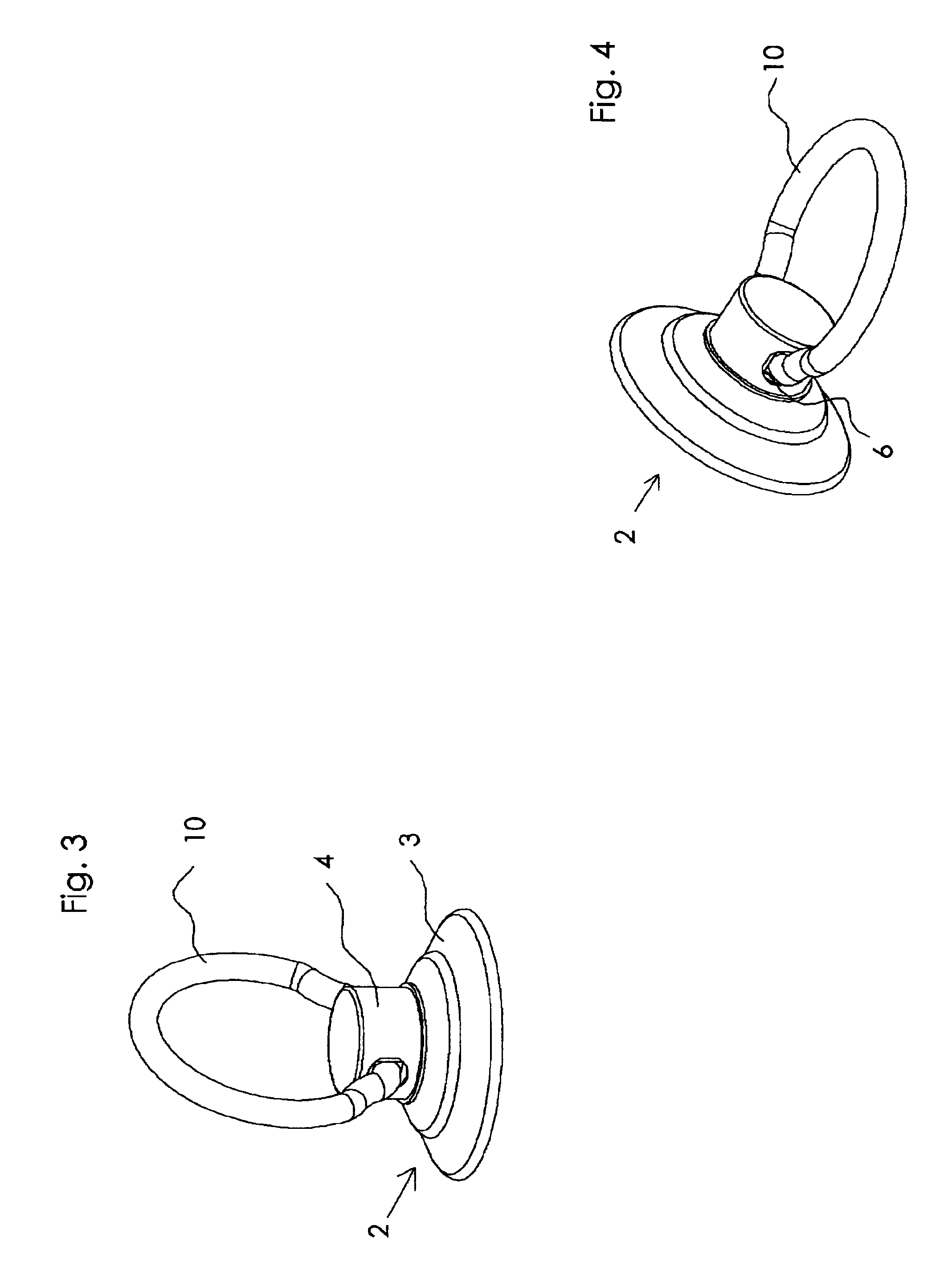
As shown in FIGS. 1 through 4, the first embodiment of my holder 1 has a suction cup 2 having a cup portion or base 3 and a cylindrical neck 4. A split ring 10 has two spaced apart end portions 14 having a square cross section. I prefer to provide a transition portion 15 between each square end 14 and the circular portion 16. The transition portion 15 which can be seen most clearly in FIG. 6 provides a larger open area 18 within the ring 10 than would be present if no transition were provided.

A bore 6 having a square cross section passes transversely through the neck 4. The square ends 12 of the split ring 10 fit within either end of the square bore in the neck 4 of the suction cup 2. The suction cup 2 is an otherwise conventional suction cup made of a soft vinyl. The neck of the suction cup may have a circular cross-section as shown or may be square, hexagonal, oval or other shape that creates a generally cylindrical structure The ring 10 is made of a harder plastic such as polypro...


PUM


Abstract

A holder for a razor or similarly shaped article has a suction cup and a split ring or a stem held within at least one bore through the neck of the suction cup. The bore and the ends of the split ring or stem have a multi-sided, preferable a square, cross section. Each side aligns with and is opposite a side of the bore keeping the split ring or stem in a selected position relative to the suction cup. When a square bore is used, the ring can be rotated 90 degrees within the bore from a plane parallel to a wall on which the suction cup could be mounted to a plane perpendicular to that wall. When a razor is placed within the ring when the ring is perpendicular to the wall, the ring will not be deflected downward.

Description

FIELD OF INVENTIONThe invention relates to holders for injector or double edge blade razors the holder being of the type having a suction cup which attaches to a wall.BACKGROUND OF THE INVENTIONA wide variety of devices for holding objects on a wall or other flat surface have been available. Many of these holders have one or more suction cups to which a basket, tray, ring, hook or similar structure is attached. For example U.S. Pat. No. 5,078,356 discloses a suction cup having an offset-mounted hook. In this device the suction cup has a cup-shaped base and cylindrical neck with a transverse circular bore. A hook has a straight cylindrical top which passes through the bore. A flat head on the top portion retains the hook in the neck of the suction cup. Because the bore and the top portion of the hook are cylindrical the hook is free to rotate within the bore. Another suction cup holder is disclosed in U.S. Pat. No. Des. 408,725. The suction cup in that holder has a cup-shaped base an...

Claims


Application Information

Patent Timeline
IPC IPC(8): A47K1/09A47K1/08F16B47/00
CPCF16B47/00A47K1/09
Inventor ADAMS, IV, WILLIAM E.
Owner ADAMS MFG
Learn More