Multipoint lock assembly

a multi-point lock and lock assembly technology, applied in the field of multi-point lock assembly for sliding doors or window sashes, can solve the problems of complex link mechanism, limited security, and relatively easy to overcome,

Inactive Publication Date: 2005-03-29
NEWELL OPERATING COMPANY
View PDF36 Cites 53 Cited by
  • Summary
  • Abstract
  • Description
  • Claims
  • Application Information

AI Technical Summary

Benefits of technology

According to another aspect of the invention, the means for allowing additional rotation allows the input device to rotate to a position defining a locked position.
According to another aspect of the invention, the operable connection between the link arm and lock member allows the link arm to move relative to the lock member to allow the input device to be further rotated to the second position after the lower lock surface contacts the lower engagement surface.

Problems solved by technology

However, it provides only a limited measure of security and can be relatively easily overcome in a forcible entry.
A disadvantage of known multipoint lock assemblies is that they are often complicated making them expensive and difficult to manufacture.
They also typically include complicated link mechanisms between moving parts along their lengths.
A further disadvantage is that multipoint lock assemblies require precise alignment between each keeper and its corresponding latch member.
If proper alignment is not achieved or maintained, the lock assembly will not function properly.
Misalignment may result in an inability of the latch mechanisms to engage the keepers or to be placed and maintained in a positively locked position.
Misalignment may also result in damage to the latches or other components.
A further disadvantage is that past lock units have been able to be activated while the door is in an open position.
If the door is then closed before moving the latches back to an open or unlocked position, damage can result to the keepers, the latches or other aspects of the lock unit.
A further disadvantage is that typical multipoint lock units and their actuators cannot accommodate for misalignment that may occur over the course of time throughout the life of the unit.
A further disadvantage is that the latch members of the lock units are not typically as sturdy or strong as one would desire to ensure an appropriate measure of security.

Method used


Image

  • Multipoint lock assembly
  • Multipoint lock assembly
  • Multipoint lock assembly

Examples


Embodiment Construction

While this invention is susceptible of embodiment in many different forms, there is shown in the drawings and will herein be described in detail preferred embodiments of the invention with the understanding that the present disclosure is to be considered as an exemplification of the principles of the invention and is not intended to limit the broad aspect of the invention to the embodiments illustrated.

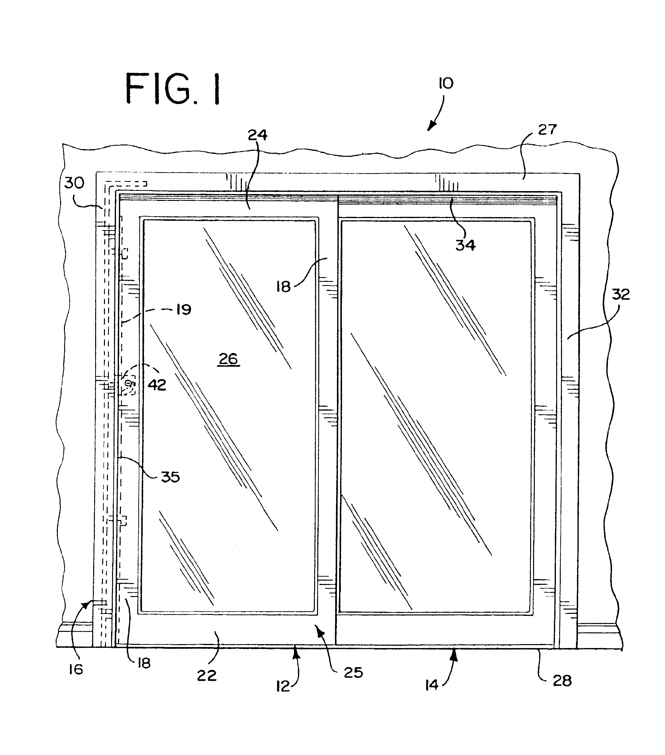
FIG. 1 shows a sliding door assembly 10 having a sliding panel 12 and a fixed panel 14 mounted within a master door frame 16. A lock assembly 42 of the present invention is shown in phantom. The sliding panel 12 is adapted for reciprocal sliding movement within the master frame 16. The fixed panel 14 remains stationary with respect to the master frame 16 and is fixed thereto. The sliding panel 12 can be considered a movable member and the door frame 16 can be considered a support frame.

The sliding panel 12 includes a pair of vertical stiles 18, and a pair of horizontal members 22 and ...


PUM


Abstract

A locking system is disclosed for a moveable member supported by a support frame, the support frame having an engagement surface, the locking system comprising a lock member and an input device adapted to be mounted on the moveable member, the input device being operably connected to the lock member. The input device is rotatable to move the lock member from a first position to a second position, the second position defining a locked position wherein the lock member is adapted to be in contact with the engagement surface. The locking system also includes a link arm and a spring that permits additional rotation of the input shaft after the lock member reaches the locked position.

Description

TECHNICAL FIELDThis invention relates generally to a lock unit for a sliding sash. More particularly, it relates to a multipoint lock assembly for a sliding door or window sash.BACKGROUND OF THE INVENTIONVarious types of sliding door or window assemblies are well known in the art. For example, a typical sliding door assembly may be used in a residential setting such as for a patio door. Such sliding door assemblies typically include two door sashes mounted within a master frame. One door sash may be stationary or remain in a fixed position relative to the master frame. The other door sash may typically be slidably mounted within the master frame. Alternatively, one or both of the door sashes can be hingedly connected to the master frame to be swinging doors.A variety of types of locking mechanisms have typically been provided for these sliding door assemblies. A simple single point lock mechanism has been provided that includes a finger that engages a keeper on the door frame, holdi...

Claims


Application Information

Patent Timeline
Patent Type & Authority Patents(United States)
IPC IPC(8): E05B15/00E05B63/00E05C9/00E05C9/02E05B65/08E05B63/18E05B15/04
CPCE05B15/0086E05B63/185E05B63/20E05C9/026E05B65/0882E05C9/185E05C9/025E05B65/087E05B15/04E05C9/1808Y10T292/0834Y10T292/432
Inventor HARGER, JAMES R.ELLERTON, TODD K.WALLS, CHRISTOPHER G.
Owner NEWELL OPERATING COMPANY
Why Eureka
Try Eureka