Vented closure

Active Publication Date: 2005-04-05
RIEKE LLC
View PDF23 Cites 63 Cited by
  • Summary
  • Abstract
  • Description
  • Claims
  • Application Information

AI Technical Summary

Benefits of technology

One object of the present invention is

Problems solved by technology

This is a laborious and inconvenient method of keeping the dishwashing machine topped up and could result in spillage of the liquid, which is often caustic, onto the

Method used


Image

  • Vented closure
  • Vented closure
  • Vented closure

Examples


Embodiment Construction

For the purposes of promoting an understanding of the principles of the invention, reference will now be made to the embodiments illustrated in the drawings and specific language will be used to describe the same. It will nevertheless be understood that no limitation of the scope of the invention is thereby intended, such alterations and further modifications in the illustrated device, and such further applications of the principles of the invention as illustrated therein being contemplated as would normally occur to one skilled in the art to which the invention relates.

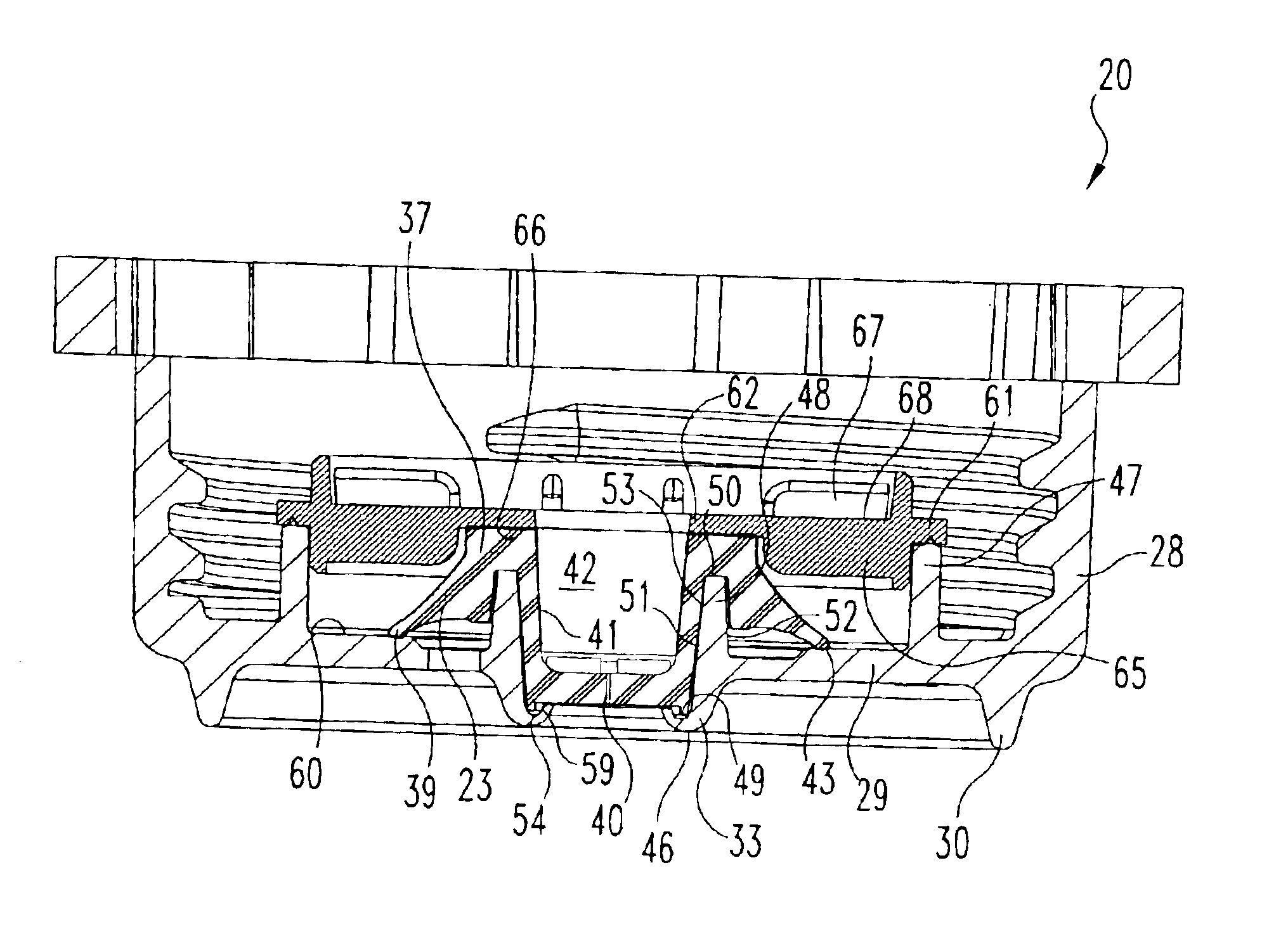
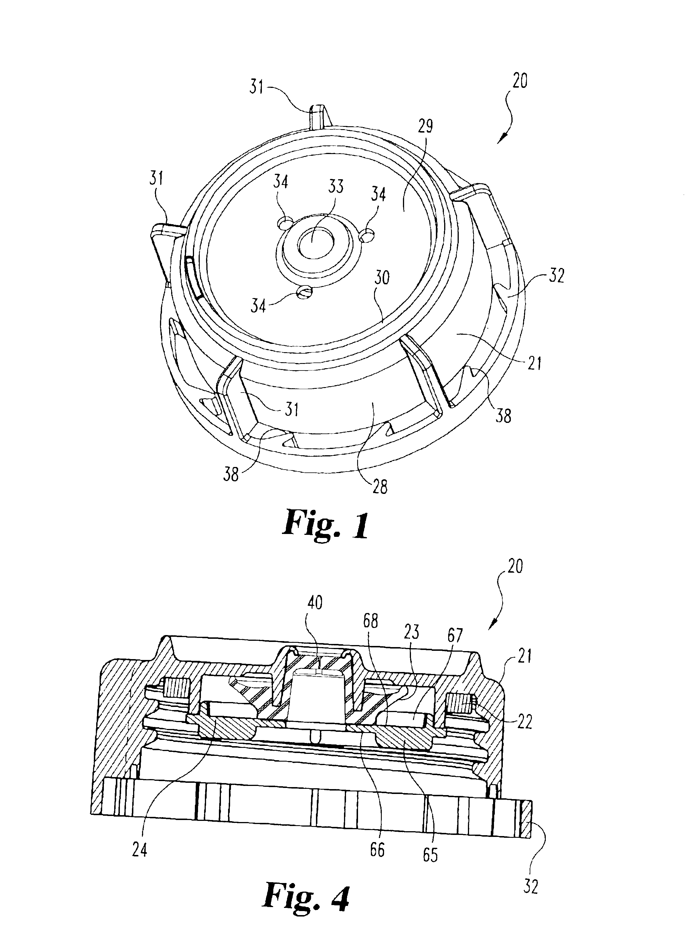
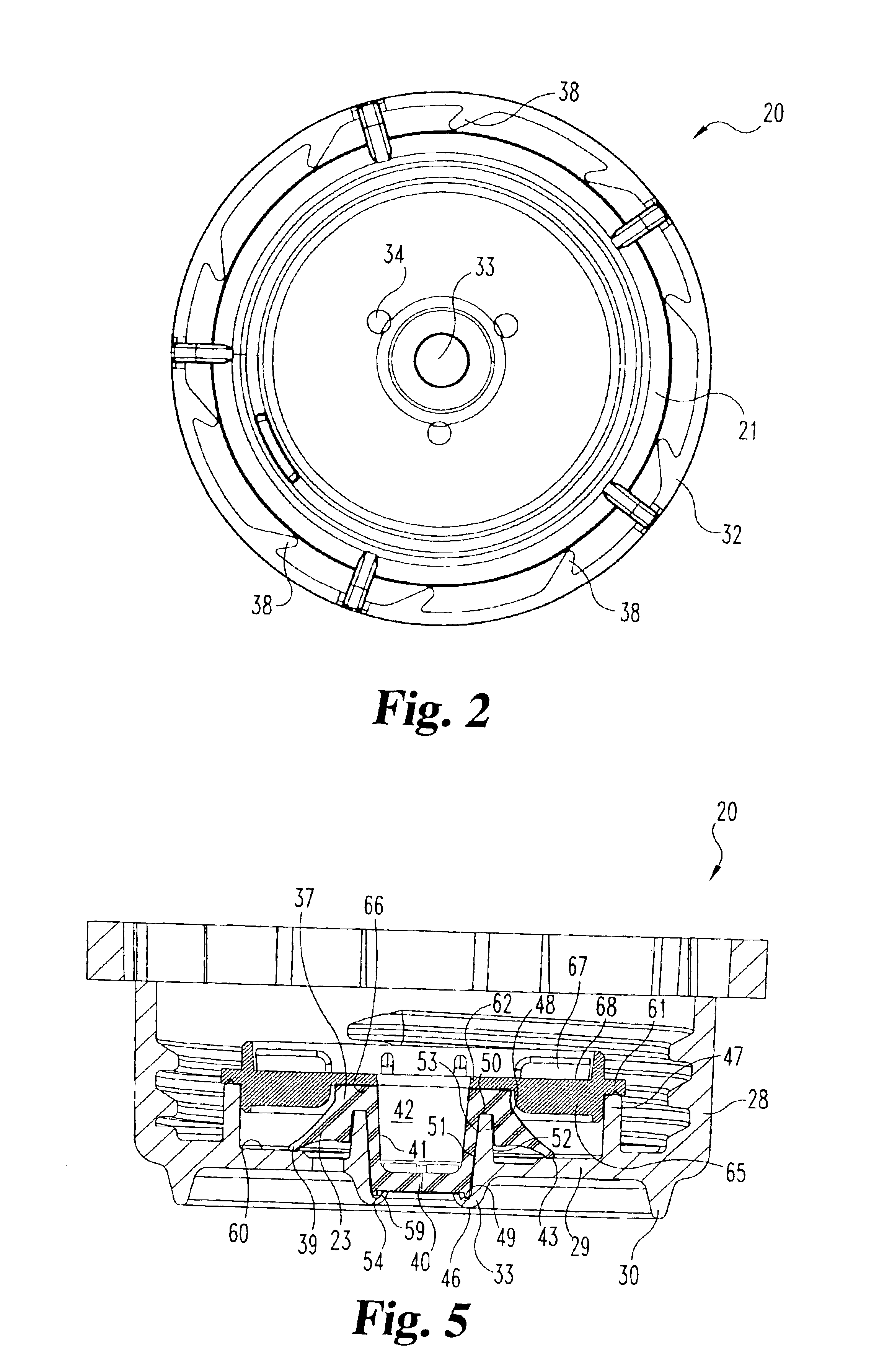
Referring to FIGS. 1-4, there is illustrated a vented closure 20 according to a preferred embodiment of the present invention. Closure 20 is an assembly of four component parts, including cap 21, gasket 22, umbrella valve 23, and retainer ring 24. Each component part is annular in shape and substantially symmetrical about its longitudinal axis. The assembly of the four component parts, as illustrated in FIGS. 3 and 4...


PUM

PropertyMeasurementUnit
Densityaaaaaaaaaa

Abstract

A vented closure for closing and venting a container with threaded engagement to a neck portion of the container for dispensing fluid from the container includes a unitary, molded plastic cap constructed and arranged for threaded engagement to the container. The threaded cap defines a septum orifice that is sized and arranged to receive a siphon tube. A gasket is assembled into the threaded cap for sealing the interfit between the vented closure and the container. An elastomeric venting valve is assembled into the threaded cap and the venting valve includes a septum with a slit therein for receiving in a self-sealing manner the siphon tube. A retainer ring is used to capture the venting valve within the threaded cap and a safety ring in unitary combination with the threaded cap retains the vented closure on the container.

Description

BACKGROUND OF THE INVENTIONThe present invention relates in general to container closures that are constructed and arranged to threadedly attach to a container opening. More specifically, the present invention relates to a container closure that is vented to allow the entry of air into the container (to relieve a negative pressure) as some of the liquid contents of the container are removed by way of an exit port. This particular closure structure can be described as a double vent closure. While the intended contents of the container are primarily liquids, slurried products can also be dispensed, as will be described herein.The present invention may find applicability in a variety of structural configurations and equipment, but the present invention is described in the context of an apparatus for dispensing a concentrated chemical in liquid form or a slurried product, such as those used for industrial cleaning processes. Additionally, the present invention is described in the contex...

Claims


Application Information

Patent Timeline
IPC IPC(8): B65D51/16A47L15/44
CPCB65D51/165
Inventor ROHR, ROBERT D.WITTE, JAY E.
Owner RIEKE LLC
Why Eureka
Try Eureka