Flapper closure mechanism

a technology of latching mechanism and latching plate, which is applied in the direction of valve operating means/release devices, wellbore/well accessories, sealing/packing, etc., can solve the problems of end failure of torsion spring, added cost of parts and labor to assemble in place, and difficulty in manufacturing parts to have the required strength

Inactive Publication Date: 2005-04-12
BAKER HUGHES INC
View PDF37 Cites 41 Cited by
  • Summary
  • Abstract
  • Description
  • Claims
  • Application Information

AI Technical Summary

Benefits of technology

A closure mechanism for a flapper features a pinion on the ear extending from the flapper that is used to mount it for pivotal movement. A spring-loaded rack meshes with the pinion or pinions on the flapper so that when the flow tube swings the flapper open, rotation ...

Problems solved by technology

The problem was end failure of the torsion springs particularly in the hook or tab area that contacted the flapper or its mounting pin.
The problem with these solutions ...

Method used


Image

  • Flapper closure mechanism
  • Flapper closure mechanism
  • Flapper closure mechanism

Examples


Embodiment Construction

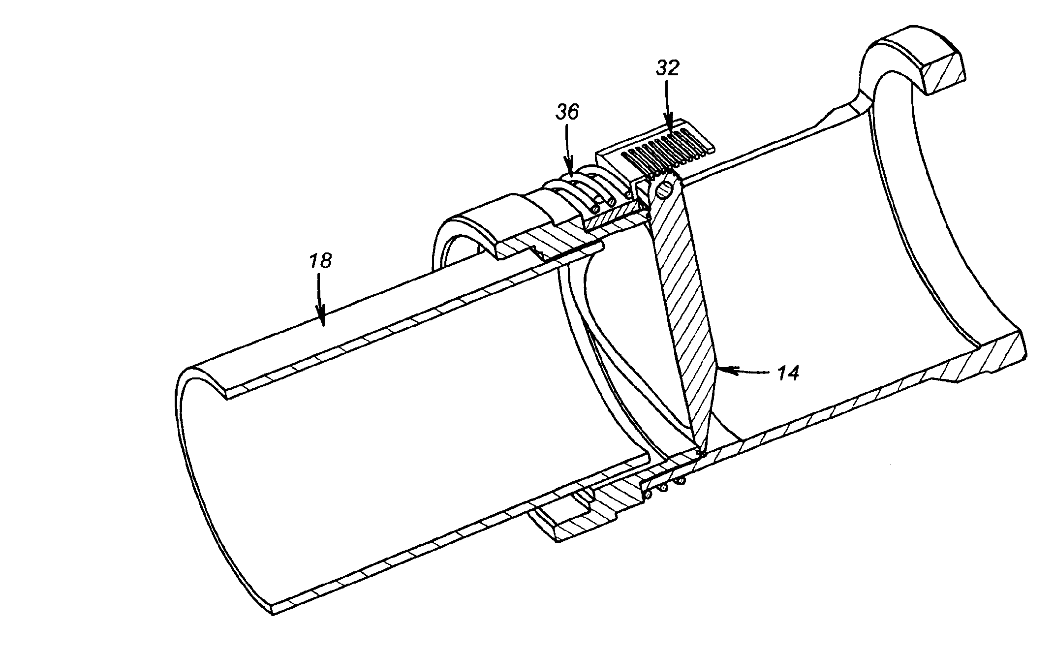
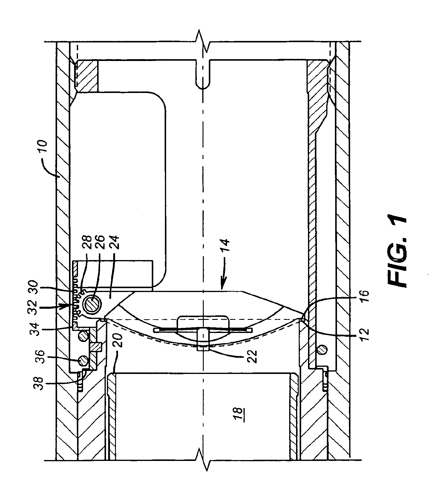
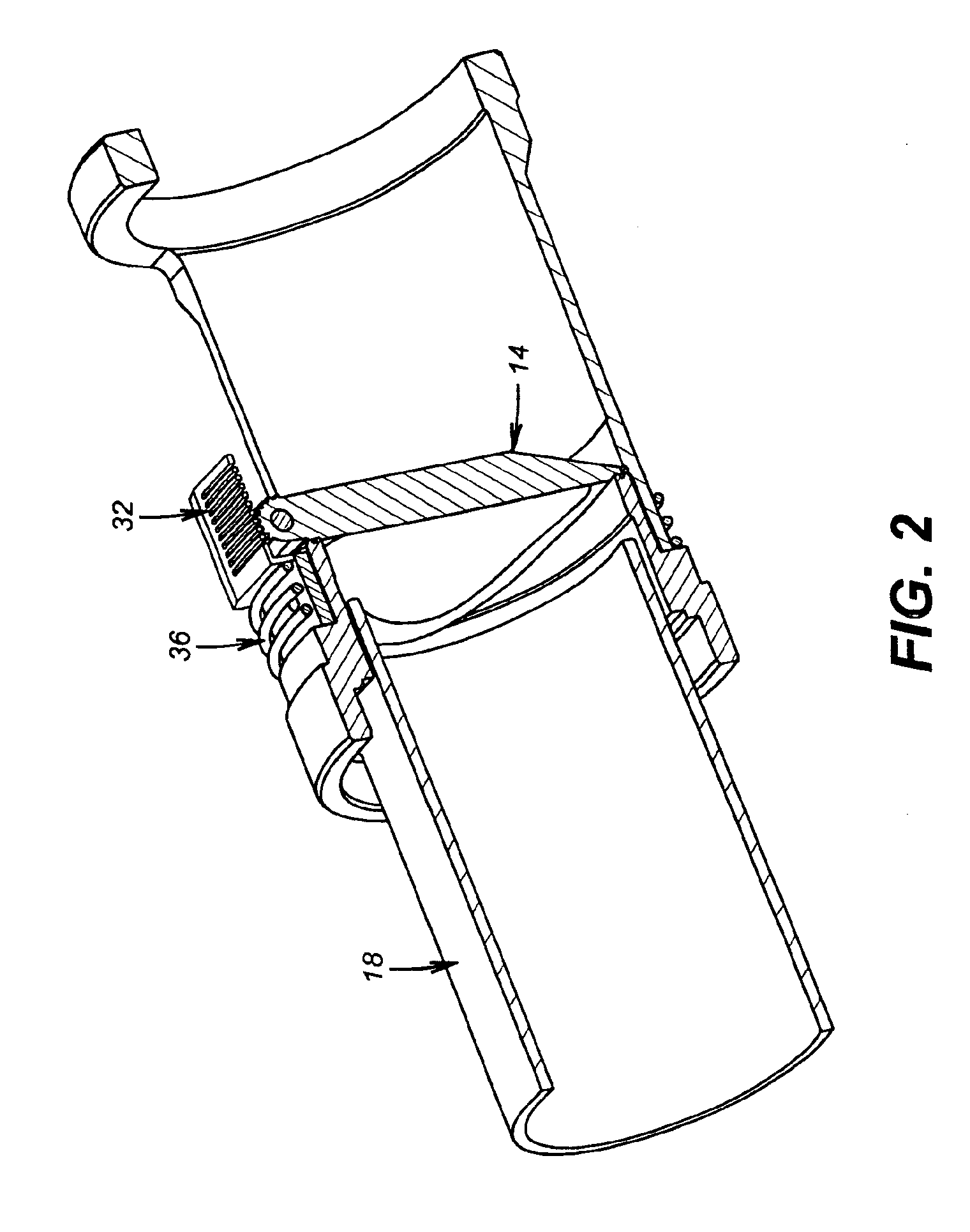
FIG. 1 illustrates the relevant portion of a safety valve needed for a complete understanding of the invention by one skilled in the art. For that reason the remainder of the valve is not illustrated. The housing 10 features a stationary valve seat 12. A flapper 14 has an edge 16 that conforms to the shape of the seat 12 to define the illustrated closed position. Flow tube 18 has a lower end 20 to contact the flapper 14 as well as the pressure equalizer piston 22. The pressure equalizer feature in flapper type valves is a feature known in the art to facilitate opening the flapper 14 by initially removing pressure differentials across the flapper 14 before the flow tube 18 tries to rotate it in a 90-degree arc. Flapper 14 has one or more ears or hinge segments 24 through which extends a mounting pin 26. Pin 26 is supported by housing 10. A series of gear teeth 28 are disposed at the periphery of ears 24 for meshing contact with gear teeth 30 forming a rack 32. Rack 32 is generally L-...


PUM


Abstract

A closure mechanism for a flapper features a pinion on the ear extending from the flapper that is used to mount it for pivotal movement. A spring-loaded rack meshes with the pinion or pinions on the flapper so that when the flow tube swings the flapper open, rotation of the pinion teeth advances the teeth on the rack against the force of a spring. When the flow tube is retracted, the spring pushes the teeth on the rack in the opposite direction causing a rotational movement of the flapper toward closure in contact with a conforming seat.

Description

FIELD OF THE INVENTIONThe field of this invention is closure mechanisms for safety valve closure members known as flappers.BACKGROUND OF THE INVENTIONSafety valves are frequently used downhole to provide emergency closure to prevent blowouts. A common design incorporates a pressurized control system involving a control line running from the surface to the valve body downhole. Pressure on the control line moves a piston connected to a hollow tube inside the valve body, known as a flow tube. A circular seat is provided for the valve member, which has a conforming shape. The valve member, known as a flapper is mounted for 90-degree rotation. When the flow tube is advanced downhole, it contacts the flapper and pushes it off the seat. The flapper winds up behind the flow tube in the wide-open position. To close the valve, pressure is removed from the control line or other control action is taken so that the flow tube is forced in an uphole direction. Eventually the flow tube clears the f...

Claims


Application Information

Patent Timeline
IPC IPC(8): E21B34/00E21B34/06E21B34/10F16K31/54F16K31/44F16K15/03F16K15/02
CPCE21B34/06E21B34/10F16K31/54F16K15/033E21B2034/005Y10T137/7898E21B2200/05
Inventor LAYTON, BEN C.ROSENBLATT, STEVE
Owner BAKER HUGHES INC
Why Eureka
Try Eureka