Snap frame arrangement

Inactive Publication Date: 2005-04-19
VISUAL CREATIONS INC
View PDF7 Cites 11 Cited by
  • Summary
  • Abstract
  • Description
  • Claims
  • Application Information

AI Technical Summary

Problems solved by technology

This display arrangement has an outer cover portion with certain defined angles which make it difficult to open the cover from its base.
The cover and the base portions are independently extruded and have a hinge relationship which requires a difficult “slide together” assembly.
This requires further operations and unnecessary manufacturing costs.
Alignment of the ends of these multiple component arrangements lead to inaccurate end mis-aligned comer sections.

Method used


Image

  • Snap frame arrangement
  • Snap frame arrangement
  • Snap frame arrangement

Examples


Embodiment Construction

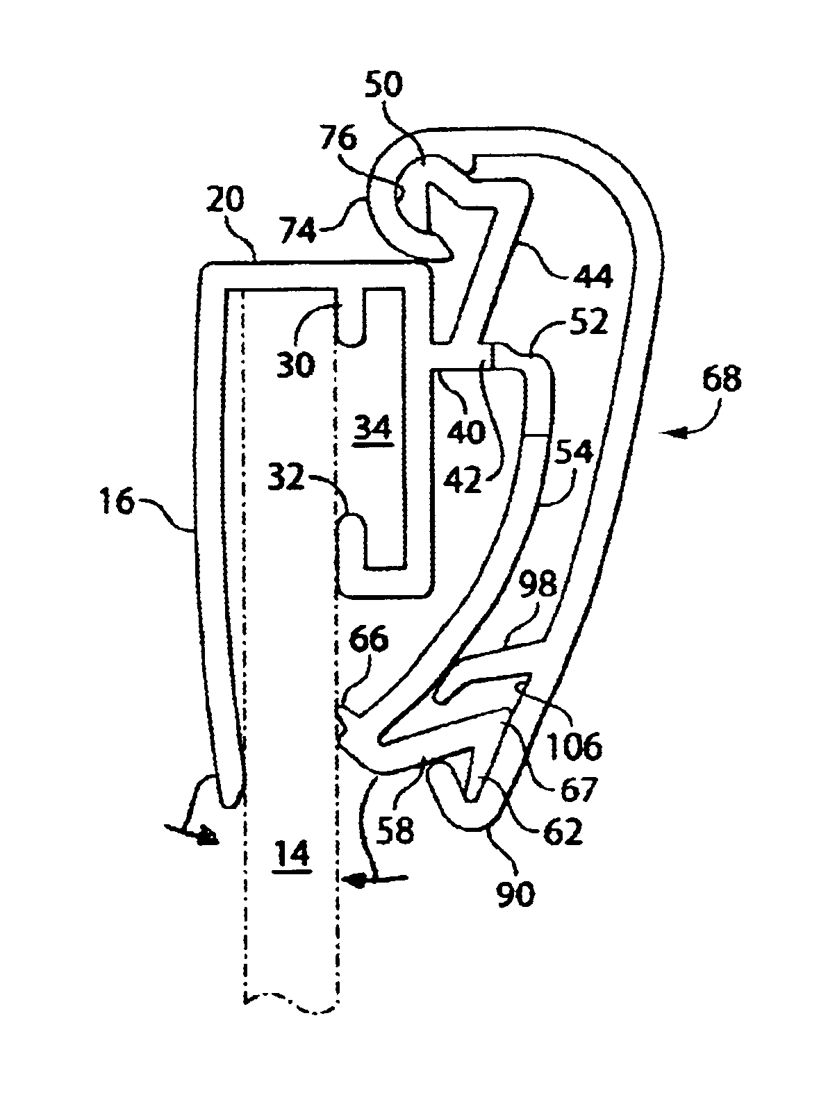
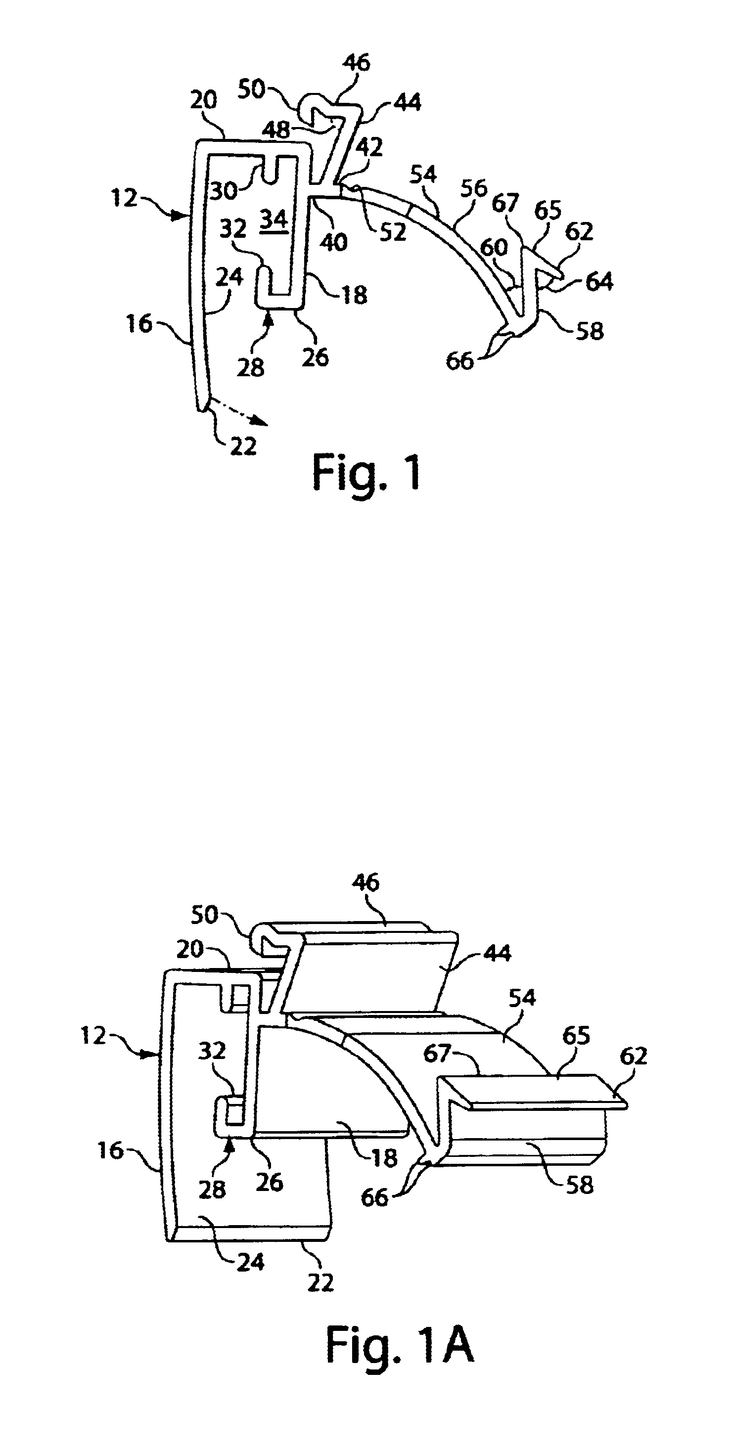
[0039]Referring now to the drawings in detail, and particularly to FIG. 1, there is shown an extruded back part 12 of the present invention which comprises a snap frame arrangement 10 for the biased capture and support of a display panel 14 (shown in FIG. 3A, 3B and 4) within that snap frame arrangement 10. The snap frame arrangement 10 may be arranged so as to show the display panel 14 from one edge, or the snap frame arrangement 10 may be arranged around its entire periphery, preferably in a quadrilateral configuration.

[0040]The snap frame arrangement 10 of the present invention includes a elongated extrusion which consists in cross-section, of a back frame plate 16 unitarily co-extruded with a front frame plate 18, shown in FIGS. 1 and 1A. The back frame plate 16 is attached and parallel to the front frame plate 18 by a connecting bridge portion 20 co-extruded therewith. The bridge portion 20 is preferably perpendicular to one edge of the back frame plate 16 and also to one edge ...


PUM


Abstract

An extruded snap frame panel arrangement assembly for the biased pinching of a display panel therewithin. The arrangement includes an elongated back frame plate, a front frame plate and a curved snap plate integrally co-extruded with the back plate and front plate, for biasedly pinching the display panel therebetween. An elongated, separately extruded cover plate is slidably attached to the curved snap plate for providing a bias to the pinching of the display panel.

Description

[0001]This application is a continuation-in-part of my commonly assigned U.S. patent application Ser. No. 09 / 820,069, filed Mar. 28, 2001, now U.S. Pat. No. 6,678,982, which is incorporated by reference herein, in its entirety.BACKGROUND OF THE INVENTION[0002]1. Field of the Invention[0003]This invention relates to extruded components for the manufacture of picture frame assemblies and poster support assemblies.[0004]2. Prior Art[0005]Poster gripping assemblies have been known in the field, for a number of years. One such instance is shown in U.S. Pat. No. 4,519,152 to Seely et. al. which shows a tamper proof poster display arrangement. This display arrangement has an outer cover portion with certain defined angles which make it difficult to open the cover from its base. An “opener tool” is required for that. The cover and the base portions are independently extruded and have a hinge relationship which requires a difficult “slide together” assembly.[0006]U.S. Pat. No. 4,937,959 to P...

Claims


Application Information

Patent Timeline
IPC IPC(8): G09F15/00
CPCG09F15/0018
Inventor BURROUS, THOMAS P.PITCHER, DAVID E.
Owner VISUAL CREATIONS INC
Why Eureka
Try Eureka