
Method and arrangement for sealing a capless fuel tank filler tube

Inactive Publication Date: 2005-04-19
EATON CORP
View PDF5 Cites 30 Cited by
  • Summary
  • Abstract
  • Description
  • Claims
  • Application Information

AI Technical Summary

Problems solved by technology

The filler tube cap has not only resulted in a relatively high manufacturing cost but has also required structure for engagement with the end of the filler tube in order to provide access for manual removal of the cap; and, this has dictated the size of the access door.

Method used


Image

  • Method and arrangement for sealing a capless fuel tank filler tube
  • Method and arrangement for sealing a capless fuel tank filler tube
  • Method and arrangement for sealing a capless fuel tank filler tube

Examples


Embodiment Construction

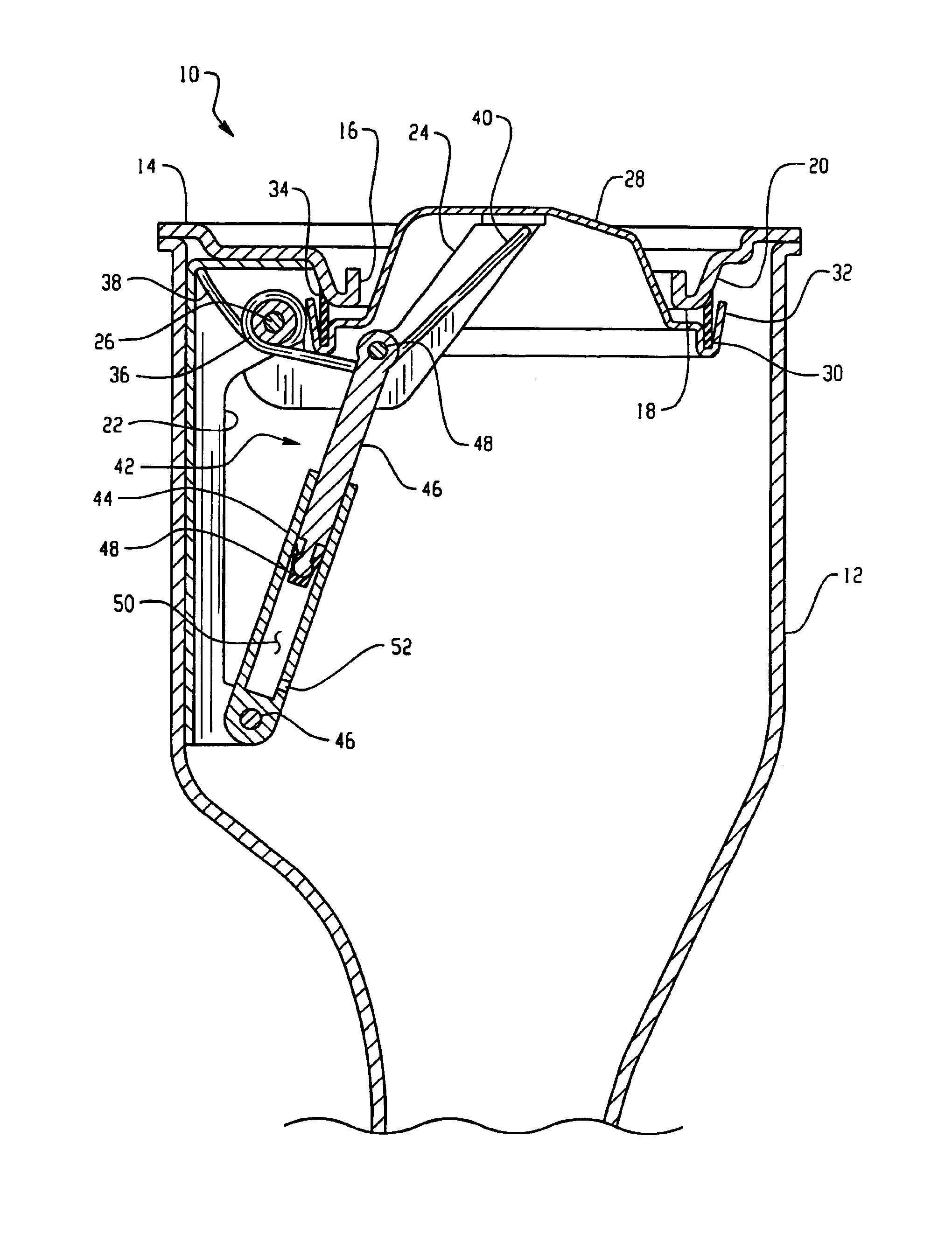
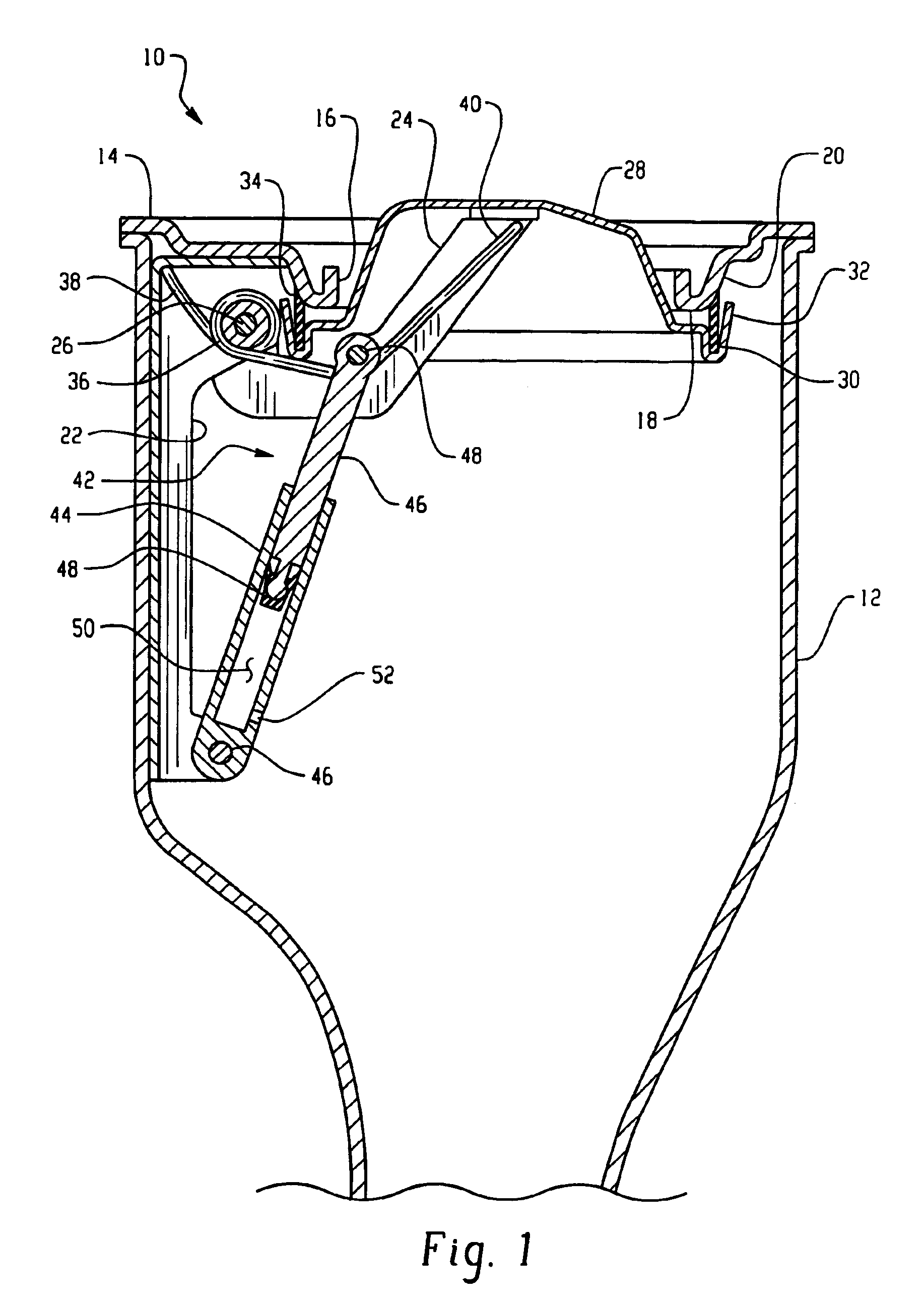
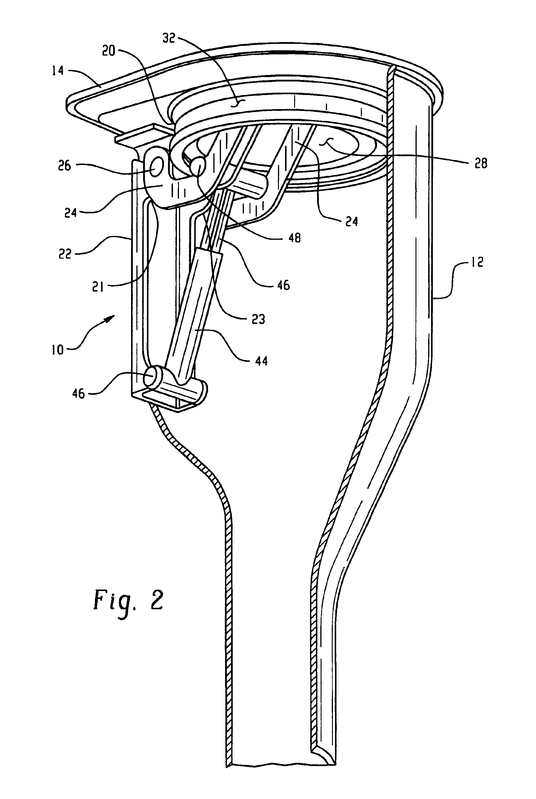
[0013]Referring to FIGS. 1, 2 and 3, the first embodiment of the invention is illustrated generally at 10 and includes a fuel tank filler tube having an enlarged upper end portion 12 with a bulkhead 14 disposed thereacross, the bulkhead having a refueling nozzle receiving aperture 16 formed therein. The aperture has an annular lip or rim 18 formed thereabout which includes an annular tapered surface 20 about the outer periphery thereof, which surface may include curvature as illustrated in FIG. 1.

[0014]The bulkhead 14 includes on the downstream or underside thereof a bracket 22 which is attached thereto and extends downwardly therefrom adjacent the outer periphery of the tapered surface 20; and, bracket 22 has a pivot arm 24 mounted on the bracket 22 for pivotal movement by any suitable expedient as, for example, pivot pin 26. The end of the pivot arm 24 distal the pivot pin 26 is attached by any suitable expedient, as for example weldment, to the undersurface of a flapper door or v...


PUM

PropertyMeasurementUnit
Electrical resistanceaaaaaaaaaa
Flexibilityaaaaaaaaaa
Speedaaaaaaaaaa

Abstract

A flapper door is spring biased closed against a valve seat on the underside of a filler tube bulkhead having a refueling nozzle aperture. The valve seat has an annular tapered surface and a resilient annular seal on the flapper door contacts the valve seat in wiping engagement. A pneumatic dampener retards the speed of closure of the flapper door onto the valve seat.

Description

BACKGROUND OF THE INVENTION[0001]The present invention relates to techniques for sealing the nozzle receiving end of a fuel tank filler tube in motor vehicle applications. The present invention particularly relates to sealing such fuel tank filler tubes which are recessed in the body structure of the vehicle and typically behind a user moveable access door or cover.[0002]Heretofore it has been widespread practice in design of motor vehicle fuel tank filler tube arrangements to provide a user moveable cover or door for providing access to the fuel nozzle receiving end of the fuel tank filler tube and to provide a removable cap or closure on the end of the filler tube. Such removable caps are typically provided with a one-way valve to permit ambient air to be drawn into the tank as fuel is withdrawn in order to prevent collapse of the fuel tank from atmospheric pressure acting thereon.[0003]The filler tube cap has not only resulted in a relatively high manufacturing cost but has also ...

Claims


Application Information

Patent Timeline
IPC IPC(8): B60K15/04
CPCB60K15/04B60K15/0406Y10S220/33B60K2015/0445G08G1/095
Inventor BENJEY, ROBERT P.
Owner EATON CORP
Learn More