Method of making a reinforcing mat for a pultruded part

Inactive Publication Date: 2005-04-19
PELLA
View PDF80 Cites 51 Cited by
  • Summary
  • Abstract
  • Description
  • Claims
  • Application Information

AI Technical Summary

Benefits of technology

[0060]FIG. 23 is a schematic illustration of a top view of an alternate reinforcing mat in accordance with the present invention.
[0061]FIG. 24 is a cross-sectional view of the reinforcing mat of FIG. 23.
[0062]FIG. 25 is a schematic illustration of a top view of an alternate reinforcing mat in accordance

Problems solved by technology

However, the transverse strength of pultruded parts is generally minimal because conventional mat fibers extend in random directions and only a small proportion of the total fiber component extends in the transverse direction.
Conventional mats also have a number of problems that interfere with the efficiencies of the pultrusion process.
First, the mat is relatively expensive.
Second, the mat

Method used


Image

  • Method of making a reinforcing mat for a pultruded part
  • Method of making a reinforcing mat for a pultruded part
  • Method of making a reinforcing mat for a pultruded part

Examples


example 1

Thermally Bonded Reinforcing Mat

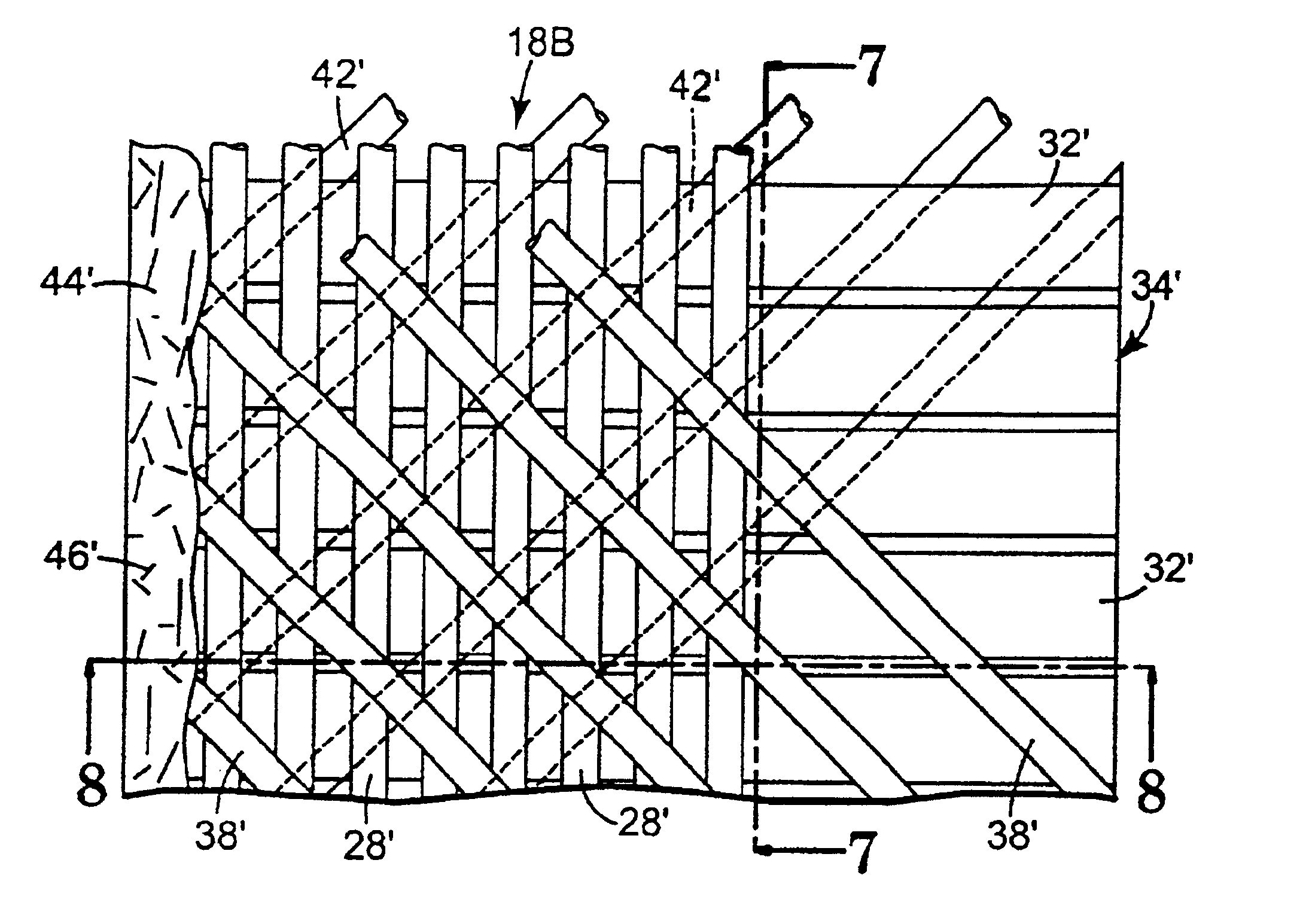
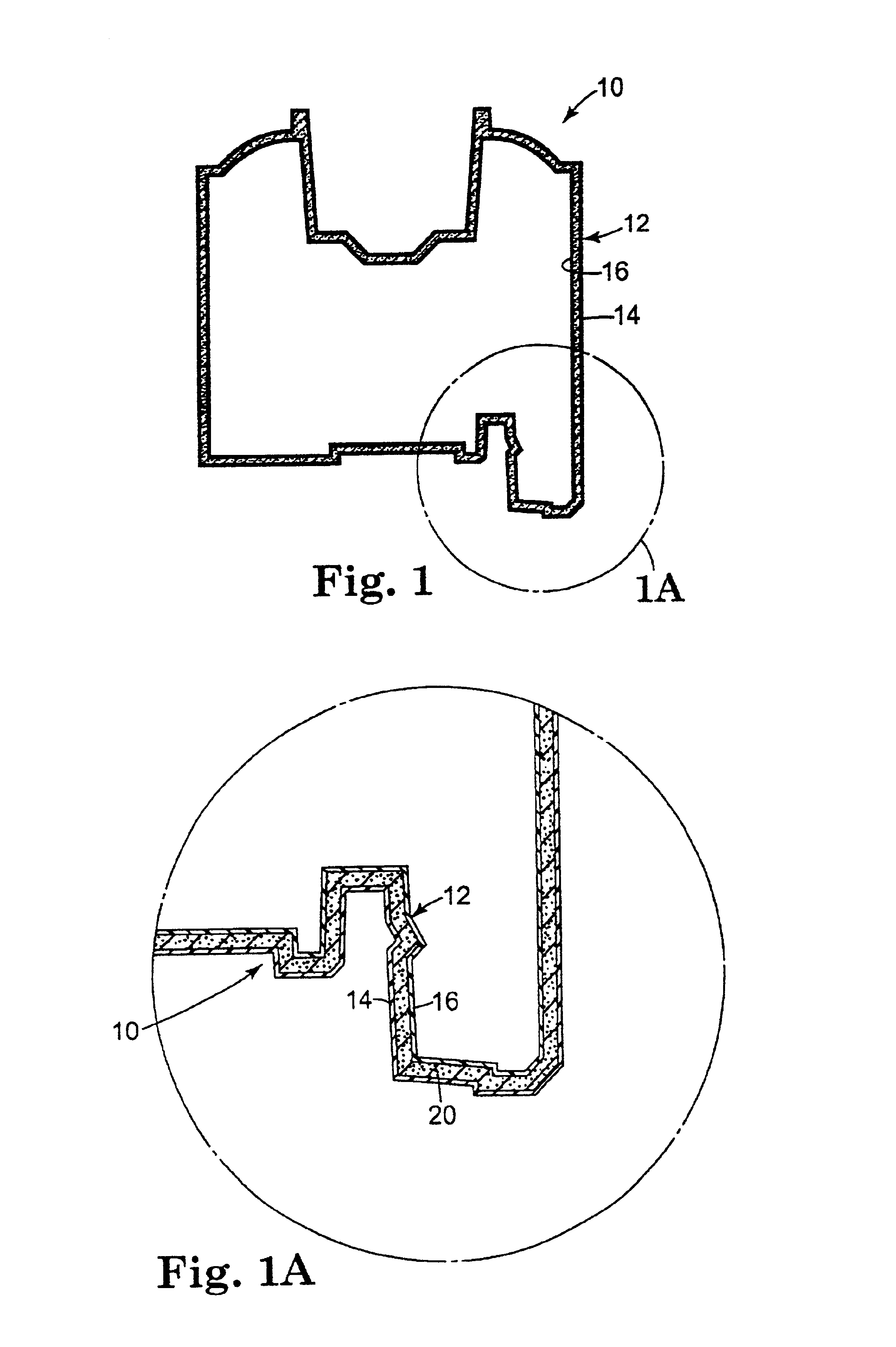
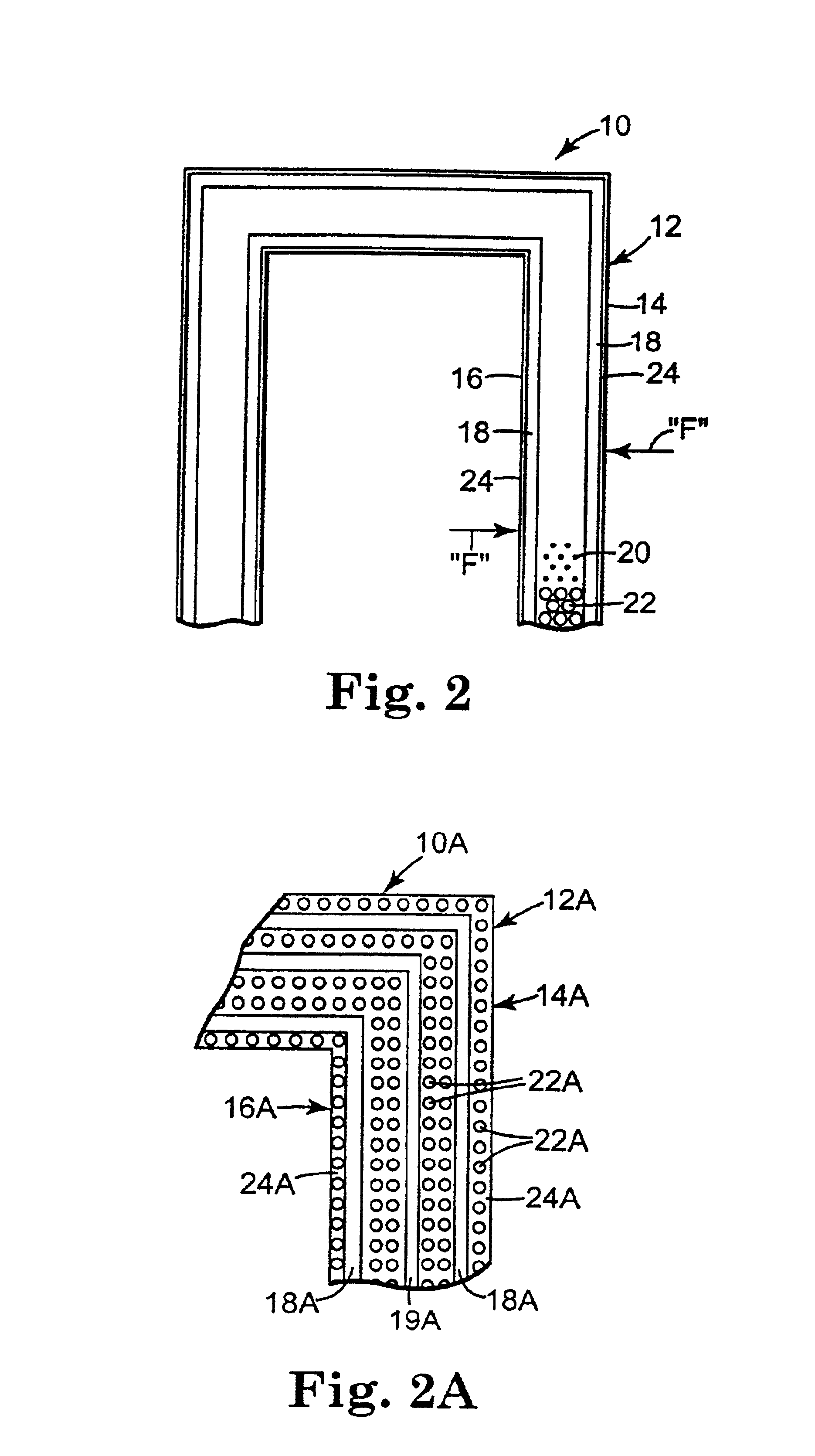
[0174]A reinforcing mat, in a resin matrix, that provides high transverse strength on the exterior or interior surface of a pultruded part such as a sash stile or rail, or a pultruded frame head, sill, or jamb, or other products outside the fenestration industry. The cross-section of the pultruded part is a matrix of thermosetting resin with longitudinal and other-reinforcing fibers in the interior of the parts profile thickness. A first mat layer accounts for about 0.010 inches of the thickness of the pultruded part, the longitudinal-reinforcing fiber area is about 0.030″ thick, and the opposite mat layer is also about 0.010″ thick. The longitudinal reinforcing fibers are oriented in the 0° direction. These longitudinal fibers are mostly 675-yield (about 675 yards per pound) glass reinforcing fibers.

[0175]The reinforcing mat is a multi-layered structure, with the longitudinal direction (e.g. the pull direction) designated as the 0°. A first layer inc...

example 2

Polyester Stitched Reinforcing Mat

[0177]A reinforcing mat, in a resin matrix, that provides high transverse strength on the exterior or interior surface of a pultruded part such as a sash stile or rail, or a pultruded frame head, sill, or jamb, or other products outside the fenestration industry. The cross-section of the pultruded part is a matrix of thermosetting resin with longitudinal and other-reinforcing fibers in the interior of the parts profile thickness. A first mat layer accounts for about 0.010 inches of the thickness of the pultruded part, the longitudinal-reinforcing fiber area is about 0.030″ thick, and the opposite mat layer is also about 0.010″ thick. The longitudinal reinforcing fibers are oriented in the 0° direction. These longitudinal fibers are mostly 675-yield (about 675 yards per pound) glass reinforcing fibers.

[0178]The reinforcing mat is a multi-layered structure, with the longitudinal direction (e.g. the pull direction) designated as the 0°. A first layer i...

example 3

Glass Fiber Stitched Reinforcing Mat

[0181]A reinforcing mat, in a resin matrix, that provides high transverse strength on the exterior or interior surface of a pultruded part such as a sash stile or rail, or a pultruded frame head, sill, or jamb, or other products outside the fenestration industry. The cross-section of the pultruded part is a matrix of thermosetting resin with longitudinal and other-reinforcing fibers in the interior of the parts profile thickness. A first mat layer accounts for about 0.010 inches of the thickness of the pultruded part, the longitudinal-reinforcing fiber area is about 0.030″ thick, and the opposite mat layer is also about 0.010″ thick. The longitudinal reinforcing fibers are oriented in the 0° direction. These longitudinal fibers are mostly 675-yield (about 675 yards per pound) glass reinforcing fibers.

[0182]The reinforcing mat is a multi-layered structure, with the longitudinal direction (e.g. the pull direction) designated as the 0°. A first layer...


PUM

PropertyMeasurementUnit
Lengthaaaaaaaaaa
Fractionaaaaaaaaaa
Fractionaaaaaaaaaa

Abstract

A method of preparing a reinforcing structure for use in manufacture a pultruded part where the reinforcing structure is pulled through a pultrusion die in a continuous longitudinal pull direction. The method includes arranging a plurality of first reinforcing fibers in a transverse direction and attaching a permeable transport web of staple fibers to the first reinforcing fibers such that the portion of the first reinforcing fibers oriented in the direction transverse comprises at least 40% of a volume of materials comprising the reinforcing structure.

Description

CROSS-REFERENCE TO RELATED APPLICATIONS[0001]The present application is a continuation-in-part of U.S. application Ser. No. 09 / 597,453, entitled Pultruded Part and Method of Preparing a Reinforcing Mat for the Part, filed Jun. 20, 2000, which claims priority of U.S. Provisional application Ser. No. 60 / 155,258 filed Jun. 21, 1999.FIELD OF THE INVENTION[0002]The present invention relates to a method of making the reinforcing mat for molded articles.BACKGROUND OF THE INVENTION[0003]Pultrusion is a known technique in which longitudinally continuous fibrous elements, which can include reinforcing fiber and / or a mat, are combined into a resin-based structure. The process generally involves pulling reinforcing fibers and / or reinforcing mats through a bath of thermoset resin and then into a heated forming die. The heat of the die cures the resin as the part is pulled through the die on a continuous basis.[0004]The mat and reinforcing fiber are typically flexible and conformable textile prod...

Claims


Application Information

Patent Timeline
IPC IPC(8): B29C70/04B29C70/50B29C70/10B29C70/52B29C70/08B29C70/24B29C70/22D04H3/04D04H3/08D04H3/12D04H3/14D04H3/02D04H3/10
CPCB29C70/081B29C70/22B29C70/24B29C70/502B29C70/506B29C70/52B29C70/521B29C70/525D04H3/04D04H3/102D04H3/12D04H3/14B32B5/28D04H1/4218D04H1/465D04H1/593B29C70/083Y10T428/24132B32B5/02B32B5/06B32B5/08B32B5/22B32B5/26B32B2250/20B32B2255/02B32B2255/24B32B2260/023B32B2260/046B32B2262/02B32B2262/06B32B2262/08B32B2262/101B32B2262/103B32B2262/105B32B2262/106B32B2262/12B32B2262/14B32B2307/50B32B2307/54B32B2307/542B32B2307/5825D04H1/4374D04H3/105D04H3/11D04H3/115Y10T442/2992Y10T442/643Y10T442/644Y10T442/659Y10T442/663
Inventor DAVIES, LAURENCE W.FRITZ, PETER J.BEER, KENNETH D.
Owner PELLA
Why Eureka
Try Eureka