Toilet flange assembly

a technology for flanges and toilets, applied in water installations, pipes, constructions, etc., can solve the problems of destroying the sealing effect of gaskets, unable to be reused, and often destroying sealing ability

Inactive Publication Date: 2005-04-26
CORNWALL KENNETH R
View PDF13 Cites 27 Cited by
  • Summary
  • Abstract
  • Description
  • Claims
  • Application Information

AI Technical Summary

Problems solved by technology

Since the seal is formed by compression of the gasket, the sealing effect of the gasket is destroyed and can be lost if the toilet becomes loose or rocks.
In addition, these gaskets were usually constructed of wax which deforms upon use and which can not be reused upon removal of the toilet.
Another disadvantage of a wax gasket is that the sealing ability is often destroyed in hot areas due to melting of the wax.

Method used


Image

  • Toilet flange assembly
  • Toilet flange assembly
  • Toilet flange assembly

Examples


Embodiment Construction

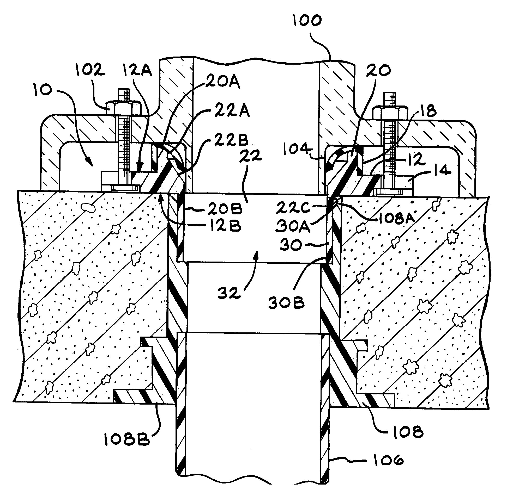
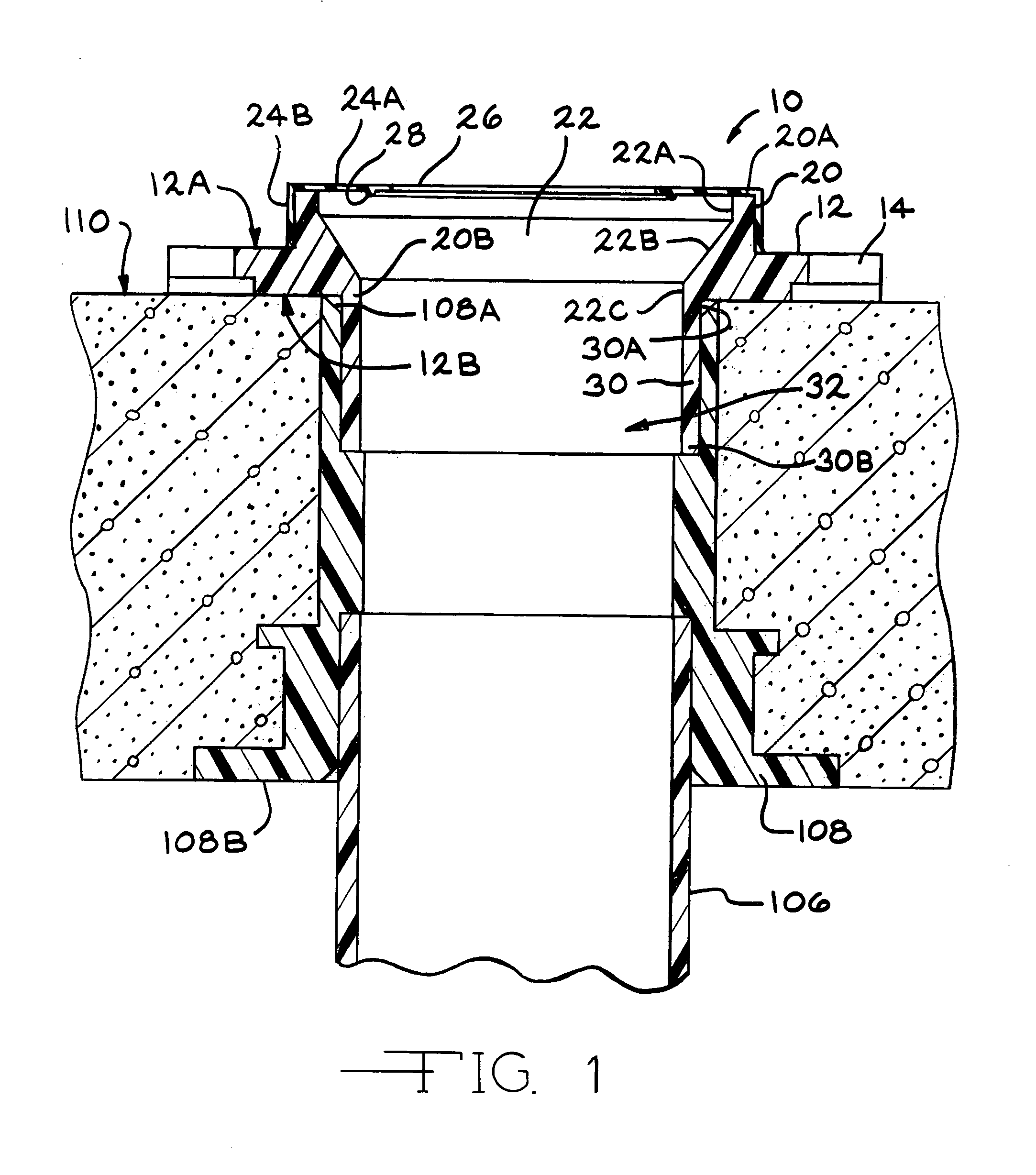
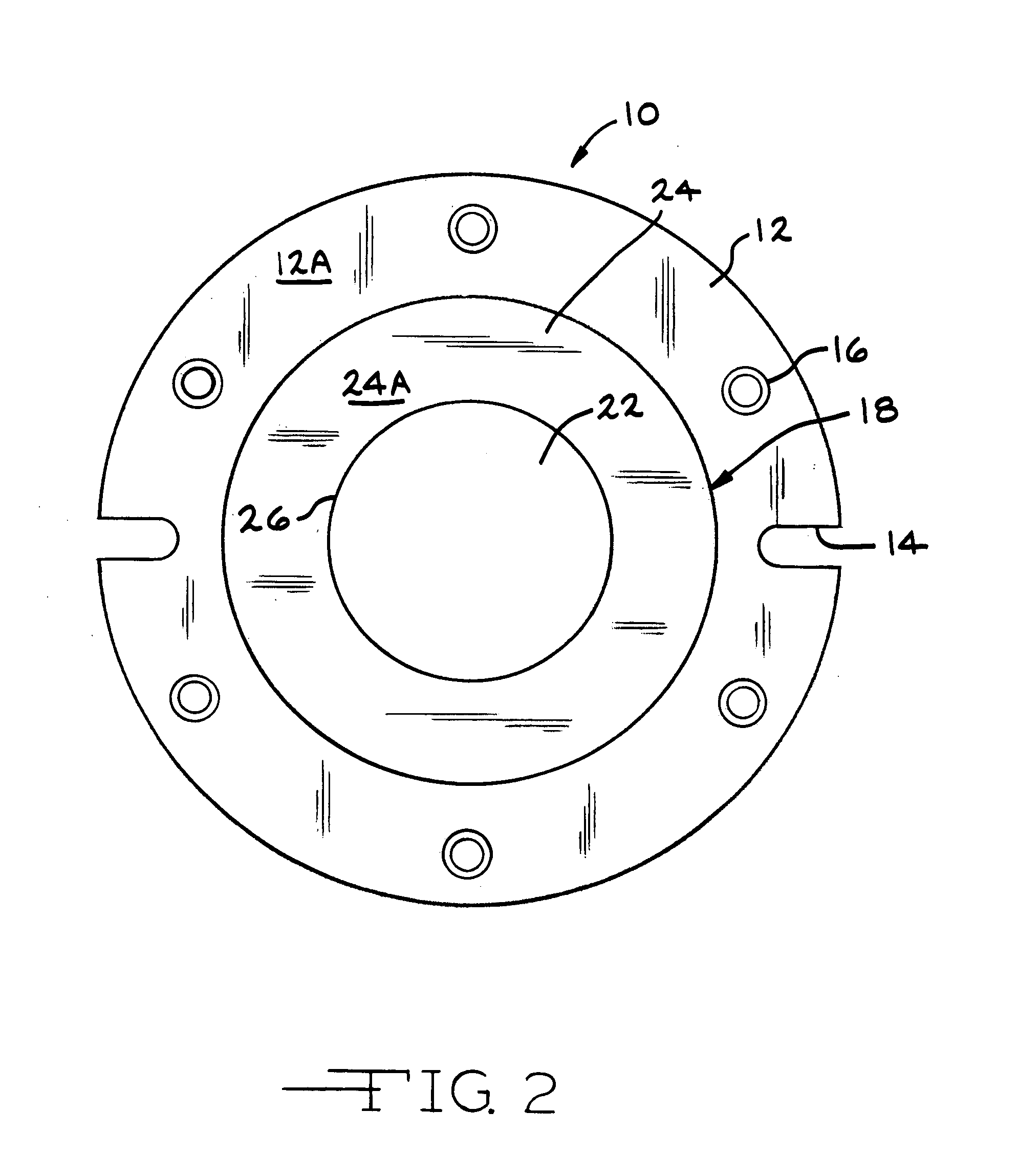
[0021]FIGS. 1 to 3 show the flange assembly 10 of the present invention. The flange assembly 10 allows for connecting the waste outlet 104 of a plumbing fixture such as a toilet 100 to a drain pipe 106 of a sewer system (not shown). The flange assembly 10 includes a ring or flange 12, an extension 20, a gasket 24 and a connector pipe 30. In one (1) embodiment, the ring 12, extension 20 and connector pipe 30 are constructed as a unitary piece. In one (1) embodiment, the ring 12, extension 20 and connector pipe 30 are constructed of an essentially rigid material such as, for example, cast iron, ABS or PVC. In one (1) embodiment, the ring 12 has a circular shape with a circular center opening 18 and is similar in shape and size to standard toilet flanges (FIG. 2). The ring 12 has slots 14 for accommodating the toilet bolts 102 which are used to secure the toilet 100 to the ring 12. The ring 12 also has holes 16 which allow the toilet 100 to be mounted to the flange assembly 10 using o...


PUM


Abstract

A flange assembly (10) for connecting a plumbing fixture to a drain pipe (106) in a fluid sealing relationship. The flange assembly includes a ring (12), an extension (20), a gasket (24) and a connector pipe (30). The extension extends outward from the top surface (12A) of the ring and the connector pipe extends outward from the bottom surface (12B) of the ring. The gasket is mounted over the end of the extension opposite the ring. The top wall (24A) of the gasket has an opening (26) which allows access to the center bore (22) of the extension. The waste outlet (104) of the plumbing fixture is inserted through the opening (26) in the top wall of the gasket into the center bore of the extension. When the waste outlet is inserted into the opening in the gasket, the gasket forms a seal between the waste outlet and the extension.

Description

CROSS-REFERENCE TO RELATED APPLICATIONS[0001]Not ApplicableSTATEMENT REGARDING FEDERALLY SPONSORED RESEARCH OR DEVELOPMENT[0002]Not ApplicableBACKGROUND OF THE INVENTION[0003](1) Field of the Invention[0004]The present invention relates to a toilet flange assembly which connects the waste outlet of a toilet with the drain pipe of the sewer system. In particular, the present invention relates to a toilet flange assembly having a resilient gasket which provides a fluid tight seal between the waste outlet of the toilet and the drain pipe.[0005](2) Description of the Related Art[0006]In the past, to prevent sewer gases and other fluids from escaping the drain pipe at the connection of the drain pipe to the plumbing fixture, a gasket was compressed between the plumbing fixture and the drain pipe. In relation to toilets, gaskets have been compressed between the underside of the base of the toilet, adjacent the waste outlet, and the toilet flange and / or between the waste outlet and the inn...

Claims


Application Information

Patent Timeline
Patent Type & Authority Patents(United States)
IPC IPC(8): E03D11/16E03D11/00
CPCE03D11/16
Inventor CORNWALL, KENNETH R.
Owner CORNWALL KENNETH R
Why Eureka
Try Eureka