Fin for heat exchanger coil assembly

a technology of heat exchanger coil and flange, which is applied in the field of flange, can solve the problems of significant affecting the heat transfer characteristics

Inactive Publication Date: 2005-05-10
EVAPCO
View PDF22 Cites 29 Cited by
  • Summary
  • Abstract
  • Description
  • Claims
  • Application Information

AI Technical Summary

Benefits of technology

[0006]The foregoing summary, as well as the following detailed description of preferred embodiments of the invention, will be better understood when read in conjunction with the appended drawings. For the purpose of illustrating the invention, there is shown in the drawings embodiments which are presently preferred. It should be understood, however, that the invention is not limited to the precise arrangements and instrumentalities shown.

Problems solved by technology

In this industry, subtle and apparently minor changes in geometry and structure significantly affect the heat transfer characteristics.

Method used


Image

  • Fin for heat exchanger coil assembly
  • Fin for heat exchanger coil assembly
  • Fin for heat exchanger coil assembly

Examples


Embodiment Construction

[0023]Certain terminology may be used in the following description for convenience only and is not limiting. The words “front,”“rear,”“left,”“right,”“top” and “bottom” designate directions in the drawings to which reference is made, where the fins are oriented vertically in a heat exchanger as shown and described hereinafter with respect to FIG. 1. The terminology includes the words specifically mentioned above, derivatives of such words and words of similar import. Furthermore, as used herein, the article “a” or “an” or a reference to a singular component includes the plural or more than one component, unless specifically and explicitly restricted to the singular or a single component, or unless otherwise clear from the context containing the term.

[0024]The invention will now be described in detail with reference to the drawings, wherein like numerals indicate like elements throughout the several views.

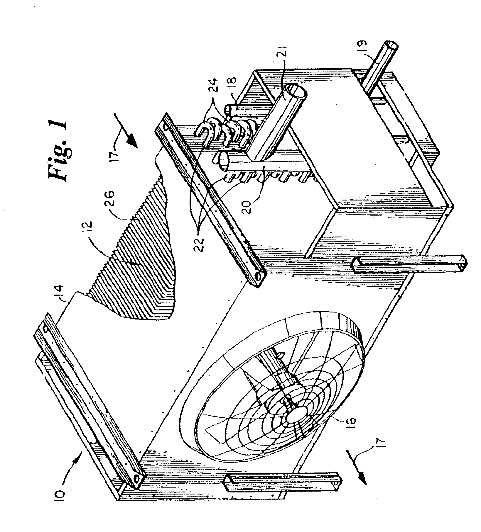
[0025]To help illustrate the environment in which the fins of the present invent...


PUM


Abstract

A fin is disclosed for use in a heat exchanger coils including tube segments extending through the fin. The fin includes a corrugated sheet of material having a plurality of major corrugations, about 8 to about 24 corrugations per inch (2.54 cm), each major corrugation being a peak or a valley with an amplitude “h” at the peaks or the valleys perpendicular to a reference major plane equally bisecting the major corrugations, and a width “w”; a plurality of orifices; a collar perpendicular to the reference major plane and extending from the sheet around each of the orifices; and a generally flat area that is generally parallel to or generally coextensive with the reference major plane and that surrounds each collar. The major corrugations have angled walls extending from at least one of the peaks and valleys to the generally flat areas adapted to create a vortex when air travels over the fin. A ratio of “h” to “w” is about 0.32 to about 0.7.

Description

BACKGROUND OF THE INVENTION[0001]The present invention relates to a fin for use as a part of a finned coil assembly for use in a heat exchanger. More particularly, the invention relates to a fin having a structure which enhances the heat exchange between the atmosphere and heat exchange fluid contained within segments of tubes passing through multiple fins of a finned coil assembly.[0002]Evaporators or plate-finned coil heat exchangers typically comprise a bundle of numerous lengths of pipe or tubing in a square or staggered array, with numerous fins in the form of plates slid over and cross-sectionally surrounding the tubes. The plate fins have holes or orifices that correspond with the tube array geometry. The heat exchanger generally includes a fan or blower that causes air to flow through the finned coil assembly where the air flows generally parallel with respect to the fins and perpendicular with respect to the tubes. Typically, the fins have a formed collar surrounding each o...

Claims


Application Information

Patent Timeline
Patent Type & Authority Patents(United States)
IPC IPC(8): F28F1/32
CPCF28F1/32Y10S165/399
Inventor DEROSIER, GREGORY S.
Owner EVAPCO
Why Eureka
Try Eureka