Single link hinge assembly with break-away link

a single link, hinge technology, applied in the direction of lighting and heating apparatus, heating types, stoves or ranges, etc., can solve the problem of more expensive manufacturing as compared to single link hinge assemblies

Active Publication Date: 2005-05-17
MANSFIELD ENGINEERED COMPONENTS
View PDF17 Cites 28 Cited by
  • Summary
  • Abstract
  • Description
  • Claims
  • Application Information

AI Technical Summary

Benefits of technology

[0011]In accordance with a first aspect of the invention, a hinge assembly comprises a claw and a channel pivotally connected to the claw at a first pivot point and adapted for movement on an arc in a first direction and in a second direction opposite the first direction. The channel is movable from a first operative position in the first direction to a second operative position, and further in the first direction to a break-away position. A link control member is connected to the channel. A spring has first and second ends, and the second end is operably engaged with the channel. A single link member defines first and second opposite contact surfaces and first and second opposite ends. The first end is pivotally connected to the claw and said second end operably engaged with the first end of the spring. The second contact surface of the link member abuts the link control member and defines: (i) a peak; (ii) an operative surface portion on a first side of the peak that cooperates with the peak to define a first dwell point; and, (iii) a break-away surface portion on a second side of the peak. The link member is movable relative to the link control member in response to pivoting movement of the channel relative to the claw. The link control member is in contact with the operative surface portion of the link when the channel is located in the first operative position; the link control member is located in the first dwell point when the channel is located in the second operative position; and, the link control member is in contact with the break-away surface portion of the link when the channel is located in the break-away position.
[0012]In accordance with another aspect of the present invention, an oven comprises a frame, a door, and at least one hinge assembly that movably connects the door to the frame. The at least one hinge assembly comprises a claw connected to the frame, and a channel connected to the door. The channel is also pivotally connected to the claw at a first pivot point and is adapted for movement on an arc in a first direction and in a second direction opposite the first direction. The channel is movable from a first operative position in the first direction to a second operative position, and further in the first direction to a break-away position, wherein: (i) the first operative position corresponds to a fully closed position of the door relative to the frame; (ii) the second operative position corresponds to a fully open operative position of the door relative to the frame; and, (iii) the break-away position corresp

Problems solved by technology

These are more expensive to manufacture as

Method used


Image

  • Single link hinge assembly with break-away link
  • Single link hinge assembly with break-away link
  • Single link hinge assembly with break-away link

Examples


Embodiment Construction

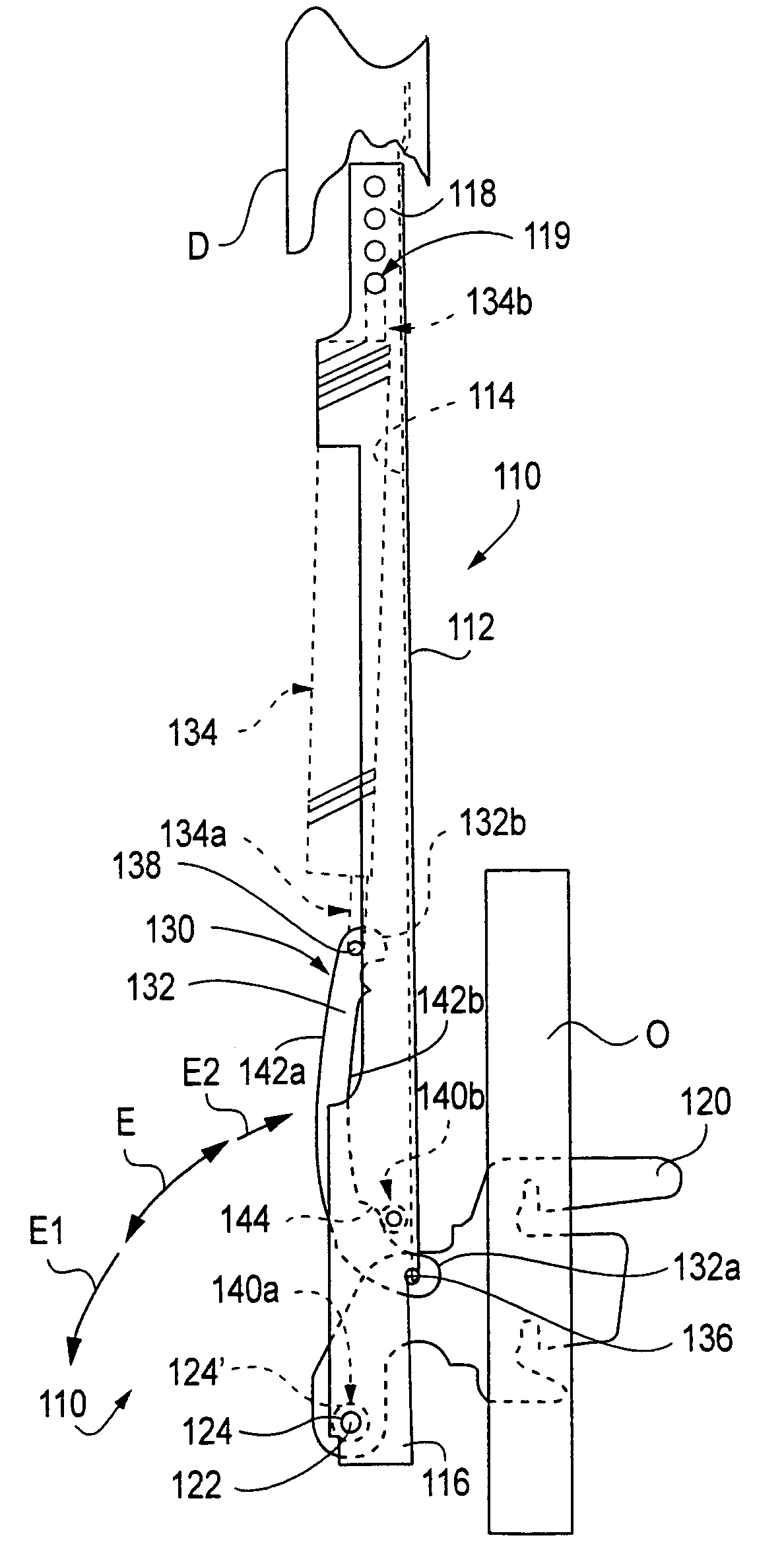
[0026]FIG. 5 shows a hinge assembly 110 formed in accordance with the present invention operatively connected a frame or chassis O of an oven or other appliance. More particularly, the hinge assembly 110 comprises an elongated channel member 112 preferably defined from a U-shaped member that defines a longitudinally extending recess 114 in a front face. The channel member 112 extends axially between first and second opposite ends 116,118.

[0027]A claw member 120 is pivotally connected to the channel 112 adjacent the first end 116 at a pivot point 122 by way of a transverse rivet or other fastener 124, and the fastener 124 supports a coaxial sleeve, bushing, roller or the like 124′ that at least partially transversely spans the recess 114 of channel 112. In this way, the channel 112 is adapted for pivoting movement relative to the claw 120 about the pivot point 122 on an arc E in respective first and second opposite directions E1,E2.

[0028]The channel 112 is movable on the arc E to an...


PUM


Abstract

A hinge assembly for connecting an appliance door to an appliance frame includes a claw and a channel pivotally connected to the claw. A single link member is pivotally connected to the claw, and the link member defines first and second contact surfaces. The second contact surface defines an operative portion and a break-away portion separated from the operative portion by a peak. A spring is operably engaged between the link member and the channel. A link control member is connected to the channel and contacts the second contact surface of the link member. The channel is movable from a first operative position in a first direction on arc of 90 degrees or less to a second operative position where the link control member is in contact with the operative portion of the second contact surface of the link. The channel is movable from the second operative position further in the first direction to a break-away position that is more than 90 degrees from the first operative position where the link control member is in contact with the break-away portion of the second contact surface of the link.

Description

BACKGROUND OF THE INVENTION[0001]U.S. Pat. No. 6,453,510, the disclosure of which is hereby expressly incorporated by reference herein, describes a single link hinge assembly. FIGS. 1–4 of the present application illustrate such a single link hinge assembly 10 as described in the U.S. Pat. No. 6,453,510. The hinge assembly 10 includes an elongated channel member 12 preferably defined from a U-shaped member that defines a longitudinally extending recess 14 in a front face. The channel member extends axially between first and second opposite ends 16,18.[0002]A claw member 20 is pivotally connected to the channel 12 adjacent the first end 16 at a pivot point 22 by way of a transverse rivet or other fastener 24. Thus, the channel 12 is adapted for pivoting movement relative to the claw 20 about the pivot point 22 on an arc E in respective first and second opposite directions E1,E2. The channel is movable on the arc E to and between a first operative position (FIGS. 1–3) and a second ope...

Claims


Application Information

Patent Timeline
IPC IPC(8): E05F1/00E05F1/12F24C15/02
CPCE05F1/1276F24C15/023E05Y2900/308Y10T16/5385Y10T16/5402Y10T16/551Y10T16/53834Y10T16/5404
Inventor HABEGGER, JEFFREY D.CUMMINS, STEVEN O.CUMMINS, BRUCE M.
Owner MANSFIELD ENGINEERED COMPONENTS
Why Eureka
Try Eureka