Exercise and therapeutic trainer

a trainer and exercise technology, applied in the field of exercise equipment, can solve the problems of not being able to provide sufficient hip flexure, not being able to provide sufficient aerobic effort, and the major axis of the path is limited to being twice the crank's length

Inactive Publication Date: 2005-06-21
CORE INDS MICHIGAN
View PDF211 Cites 71 Cited by
  • Summary
  • Abstract
  • Description
  • Claims
  • Application Information

AI Technical Summary

Benefits of technology

[0023]This is done through a motor drive including a D.C. brush motor. The D.C. brush motor turns the cranks of the trainer thereby turning the foot links and pedals through the linkage. This causes the patient's legs to move in response to being placed on the foot pedals. The particular desired movement can be adjusted to a particular speed of walking depending upon the level of capability by the patient.
[0024]Additionally, the D.C. brush motor can be overdriven by the patient when the patient is able to exert an effort. This overdrive allows the patient to move in a particular manner and exert a certain force on the pedals. The pedals can then be controlled in the overdrive mode and provided with a particular force through a resistance on the D.C. brush motor or other suitable resistance.

Problems solved by technology

However, they are considered impact devices which in some cases are not as beneficial to the user as for example a low impact device such as a bicycle whether it be a reclining or vertical bicycle or such stepping machines as are known in the art.
One of the drawbacks of such modified elliptical paths is that the major axis of the path is limited to being twice the crank's length.
This does not provide sufficient aerobic effort nor provide for enough hip flexure to maximize a cardiovascular workout through the leg, hip, quadriceps, and other muscle portions of the body.
Also, when used as a physical therapy device, it is cumbersome, bulky, high, and difficult for a patient to use.

Method used


Image

  • Exercise and therapeutic trainer
  • Exercise and therapeutic trainer
  • Exercise and therapeutic trainer

Examples


Embodiment Construction

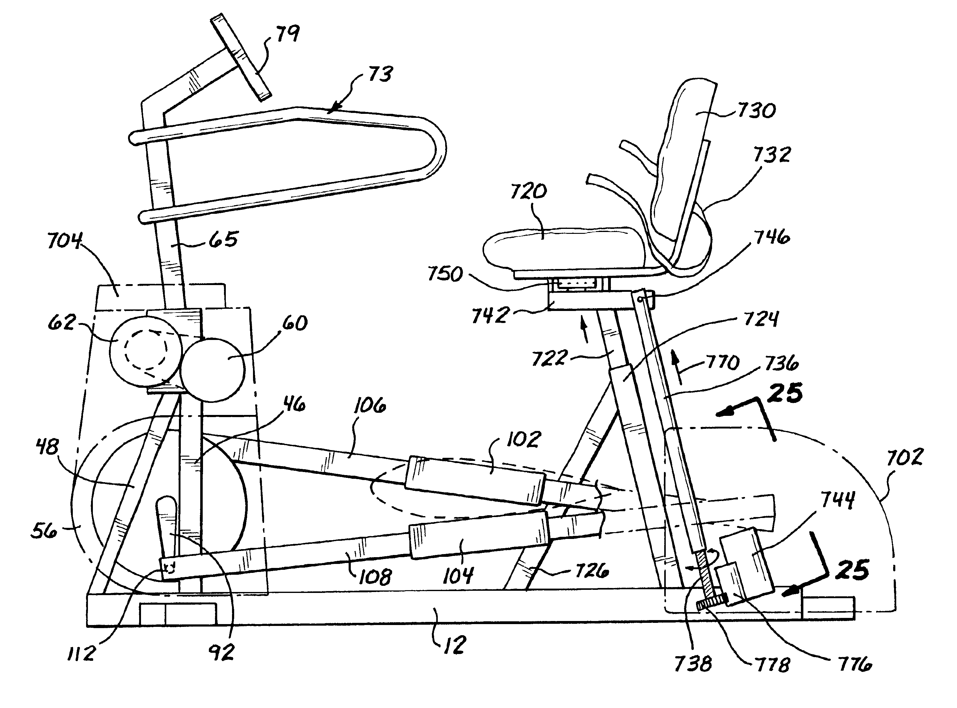
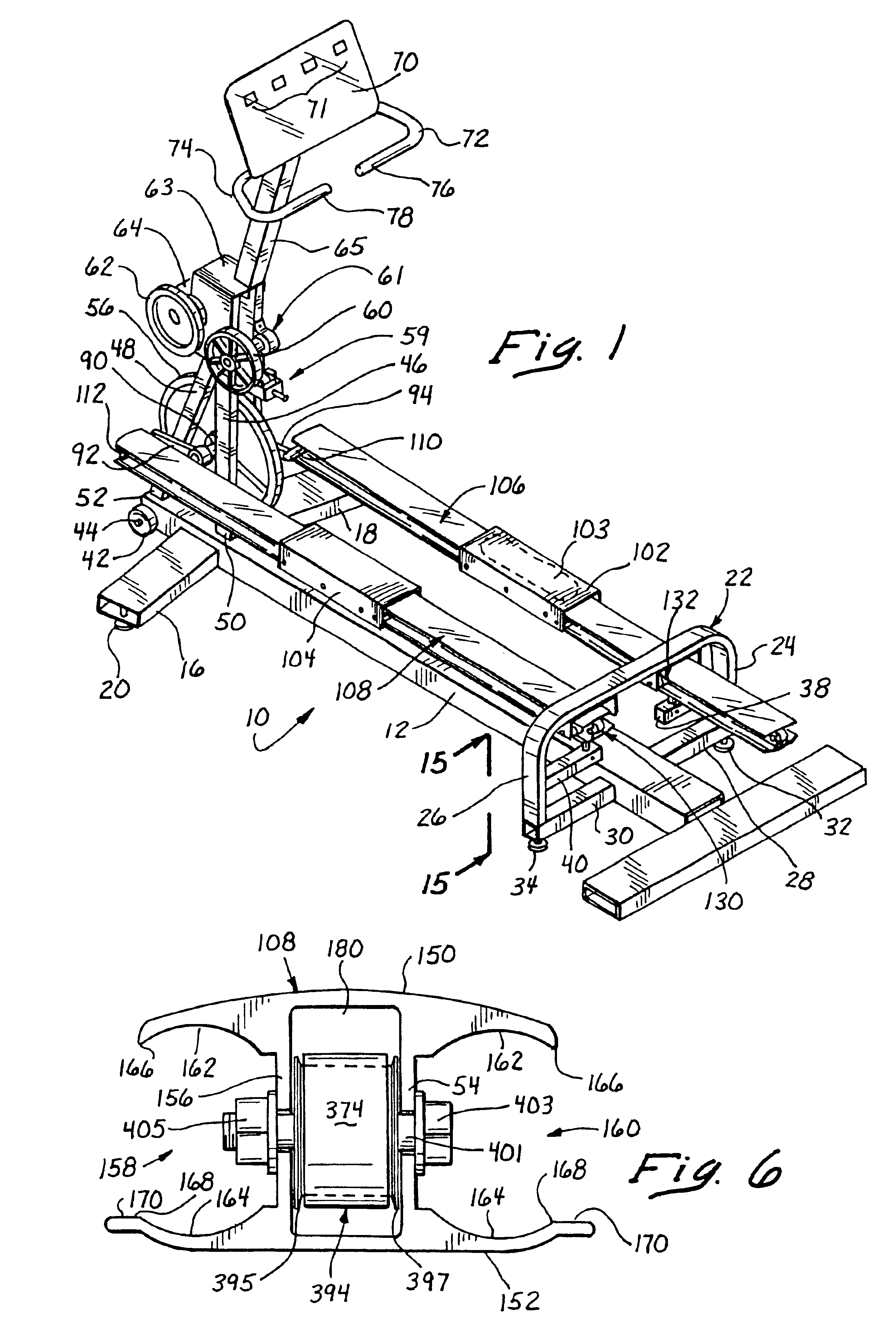
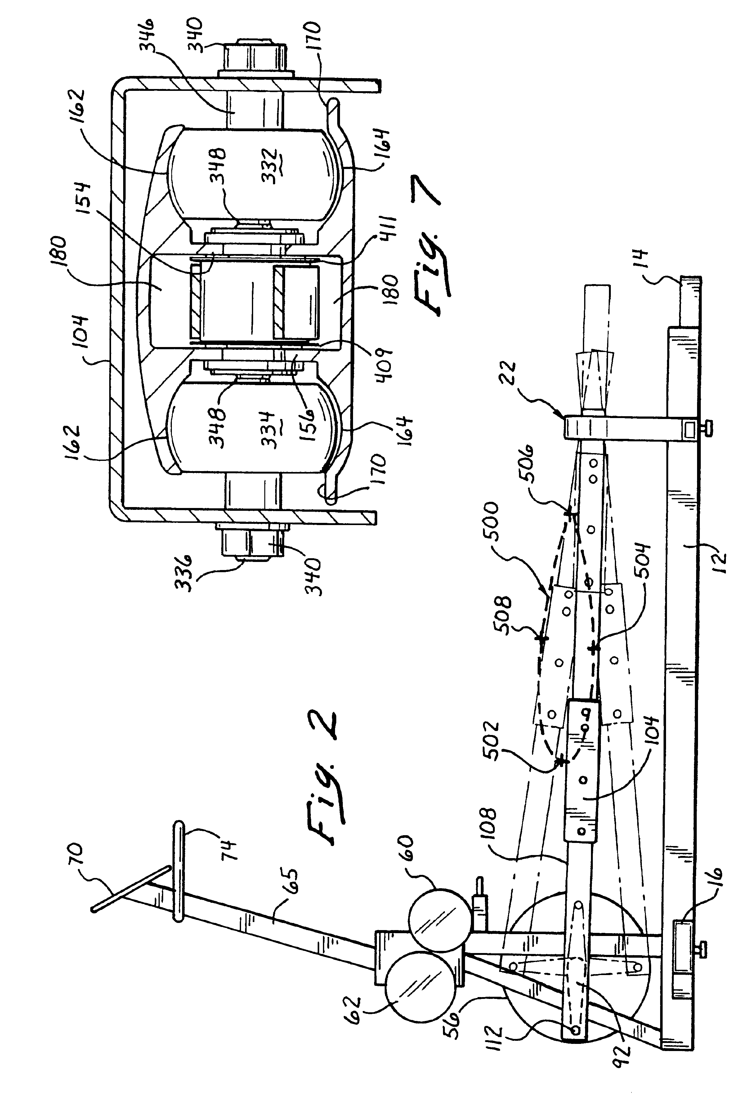
[0054]Looking more particularly at FIG. 1, which is a perspective view showing the exercise trainer of this invention, it can be seen that a frame 10 is generally shown having a longitudinal base member 12. The longitudinal base member 12 terminates at an end portion 14 forming a T shaped cross member at the rear thereof.

[0055]At the front, a pair of angular cross members 16 and 18 are shown. These angular cross members 16 and 18 are welded to the longitudinal frame member 12. Angular cross members 16 and 18 have leveling pads 20 on either side. The leveling pad of cross member 18 is hidden from view but is identically placed as the leveling pad 20 of cross member 16. These tend to level and orient the frame 10 and the attendant exerciser supported thereon.

[0056]In order to support the foot links at the rear, an inverted U shaped frame 22 is provided. The inverted U shaped frame member 22 has a horizontal portion and two depending portions 24 and 26. These vertical or upright portio...


PUM


Abstract

An exercise trainer having a first crank arm and a second crank arm respectively connected to a first foot link and a second foot link with foot pedals supported on the foot links, and bearing supports for the foot links removed from the crank arms. A flexible connection connects a ground point, the foot pedals, and the foot links to provide relative movement in a modified ellipse as to the ground point of at least twice the length of each crank arm. A seat is mounted on the trainer having a motor and control for raising and lowering the seat with respect to the foot pedals. The first and second crank arms are connected to a motor for driving the crank arms at a given speed which can supplement a user's effort or provide a load to a user beyond a given speed.

Description

[0001]This application claims the benefit of U.S. Provisional Application No. 60 / 093,927 as filed Jul. 23, 1998, which is a CIP of U.S. patent application Ser. No. 09 / 249,189 filed Feb. 12, 1999 now U.S. Pat. No. 6,183,398 B1 issued Feb. 6, 2001 and a CIP of U.S. patent application Ser. No. 09 / 740,445 filed Dec. 19, 2000 now U.S. Pat. No. 6.575,877.BACKGROUND OF THE INVENTION AND PRIOR ART[0002]1. Field of the Invention[0003]This invention pertains to exercise apparatus which is in the form of a trainer that provides a simulated walking or running stride. The trainer of this invention falls within the field of exercise and therapeutic devices such as stepping machines, simulated cross country ski machines, stationary bicycles, as well as other types of exercise trainers. It more particularly relates to those types of exercise trainers within the art and background related to pedals that can be reciprocated as attached to a pair of cranks to provide for a simulated walking or running...

Claims


Application Information

Patent Timeline
Patent Type & Authority Patents(United States)
IPC IPC(8): A63B23/04A63B23/035A63B22/04
CPCA63B21/00181A63B22/001A63B22/0664A63B21/0051A63B21/0053A63B21/225A63B2208/0233A63B2022/067A63B2022/0676A63B2022/0682A63B2022/206A63B2208/0204
Inventor MERCADO, FREDRUFINO, JOHN C.GOH, YONG MING
Owner CORE INDS MICHIGAN
Why Eureka
Try Eureka