Mooring device

a mooring device and a technology of a stern are applied in the field of mooring devices, which can solve the problems of inability to absorb the force acting on the vessel in the fore and aft directions, the prehensile assembly is not adapted to be quickly disengaged, and the vessel must be specially adapted, so as to achieve the effect of simple and effective operation and maintenance, and minimum care or adjustmen

Inactive Publication Date: 2005-06-28
CAVOTEC MOORMASTER
View PDF26 Cites 19 Cited by
  • Summary
  • Abstract
  • Description
  • Claims
  • Application Information

AI Technical Summary

Benefits of technology

[0047]Advantageously, this mooring device is simple and effective to operate and maintain, is free of interference with equipment and mechanisms utilised in the loading and unloading operations, and requires minimum care or adjustment when in use.
[0048]The mooring system also has the advantage of eliminating the need for close-in manoeuvring on departure from the dock as the mooring robots can be used to push a vessel clear of the dock. As with the mooring process, the departure is automated and can be remotely controlled.
[0049]Additionally, the use of resilient restorative forces in the horizontal plane and the resultant degree of control over vessel movement when docked, said vessel movement resulting from externally applied forces, is greatly increased over the prior art mooring devices.

Problems solved by technology

A disadvantage of this type of system is that the vessel must be specially adapted.
The prehensile assembly is not adapted to be quickly disengaged during the departure process.
Such a system is significantly more efficient than the traditional mooring process but because of the bearing plate, it is only suited to applications where the ship has a dedicated dock.
Where such is not the case, this inability to absorb forces acting on the vessel in the fore and aft direction and the necessity to provide a means of raising and lowering the dock mounted attachment plate is a disadvantage of this known system.
In both of these systems (in U.S. Pat. Nos. 3,463,114 and 3,974,794) the ship is rigidly fixed to the mooring station in the longitudinal direction with respect to the ship, consequently the mooring device is subject to deleterious impact loads in this direction.
However there is no means for mooring a vessel, nor retain the moored vessel against a dock.

Method used


Image

  • Mooring device
  • Mooring device
  • Mooring device

Examples


Embodiment Construction

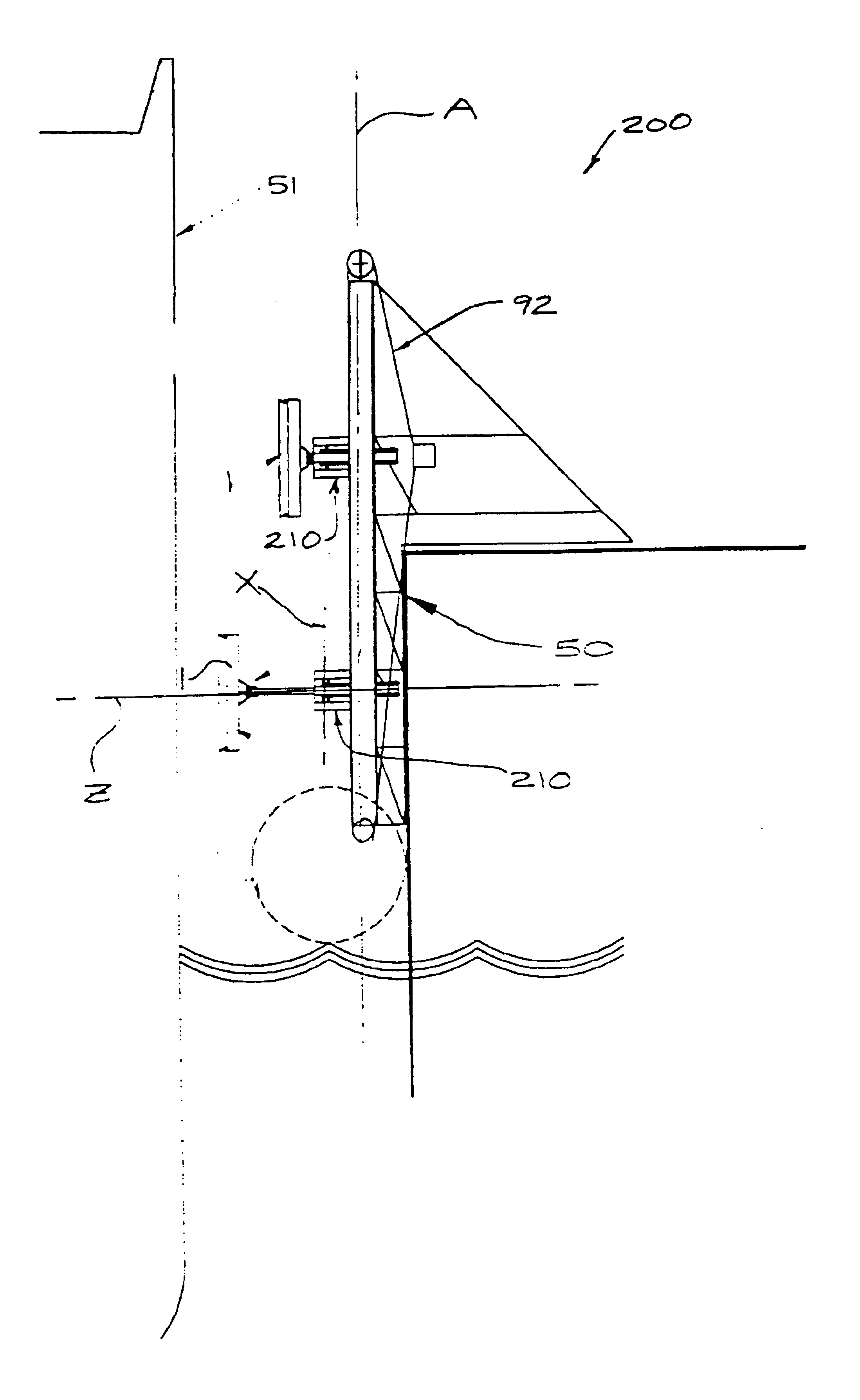
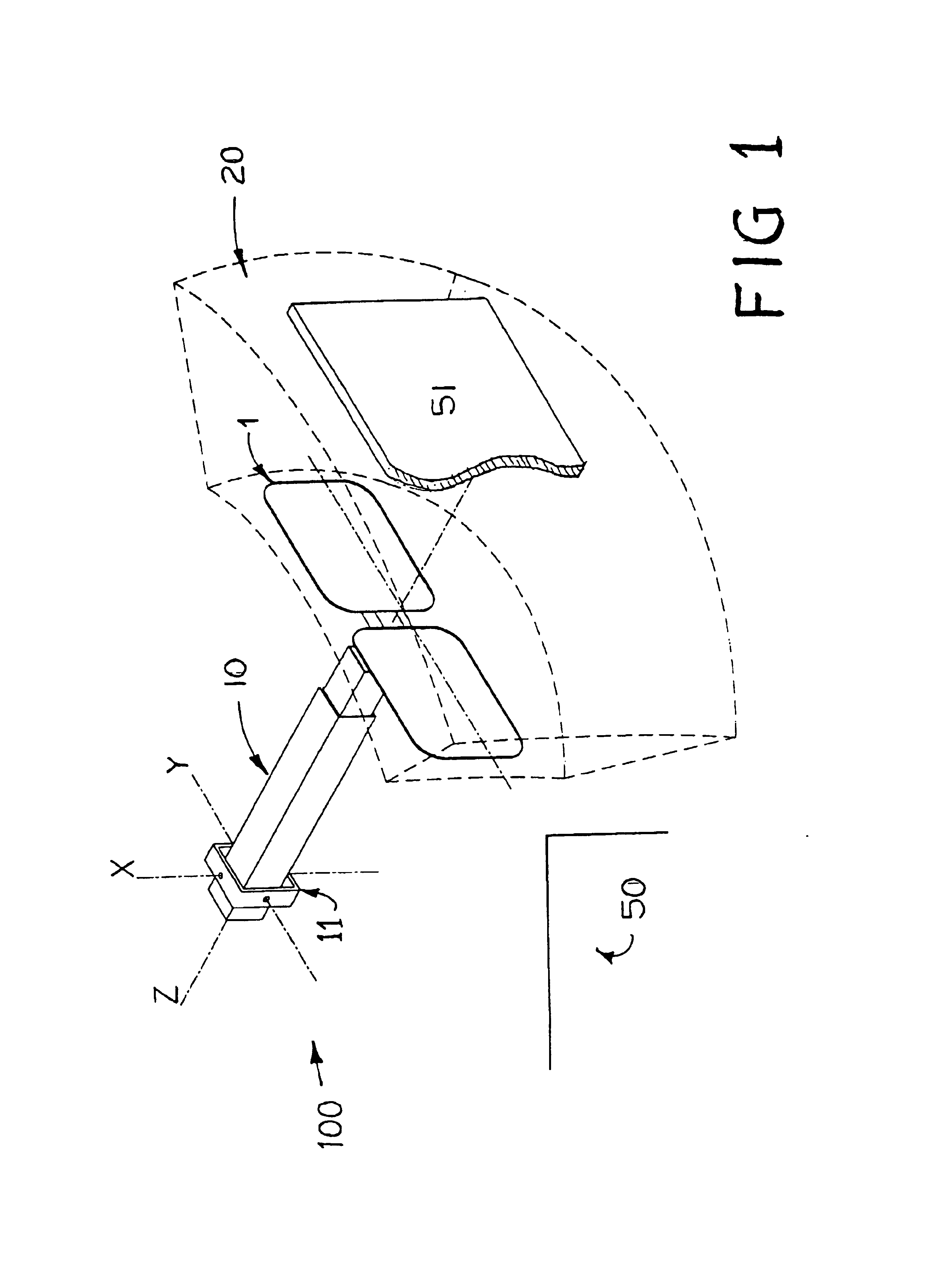
[0059]Referring to FIG. 1, a first preferred embodiment of a mooring robot 100 of the present invention (illustrated schematically) is fixed to a dock 50 and may be fastened to the hull 51 of a vessel by means of vacuum cups 1. The mooring robot 100 includes a robot arm 10, having three degrees of translational freedom for positioning the vacuum cups 1 anywhere within a three-dimensional operating envelope 20. The robot arm 10 provides a telescoping movement along axis Z and is fixed at one end in a gimbal 11 for rotation about two orthogonal axes X and Y, which are substantially vertical and horizontal respectively.

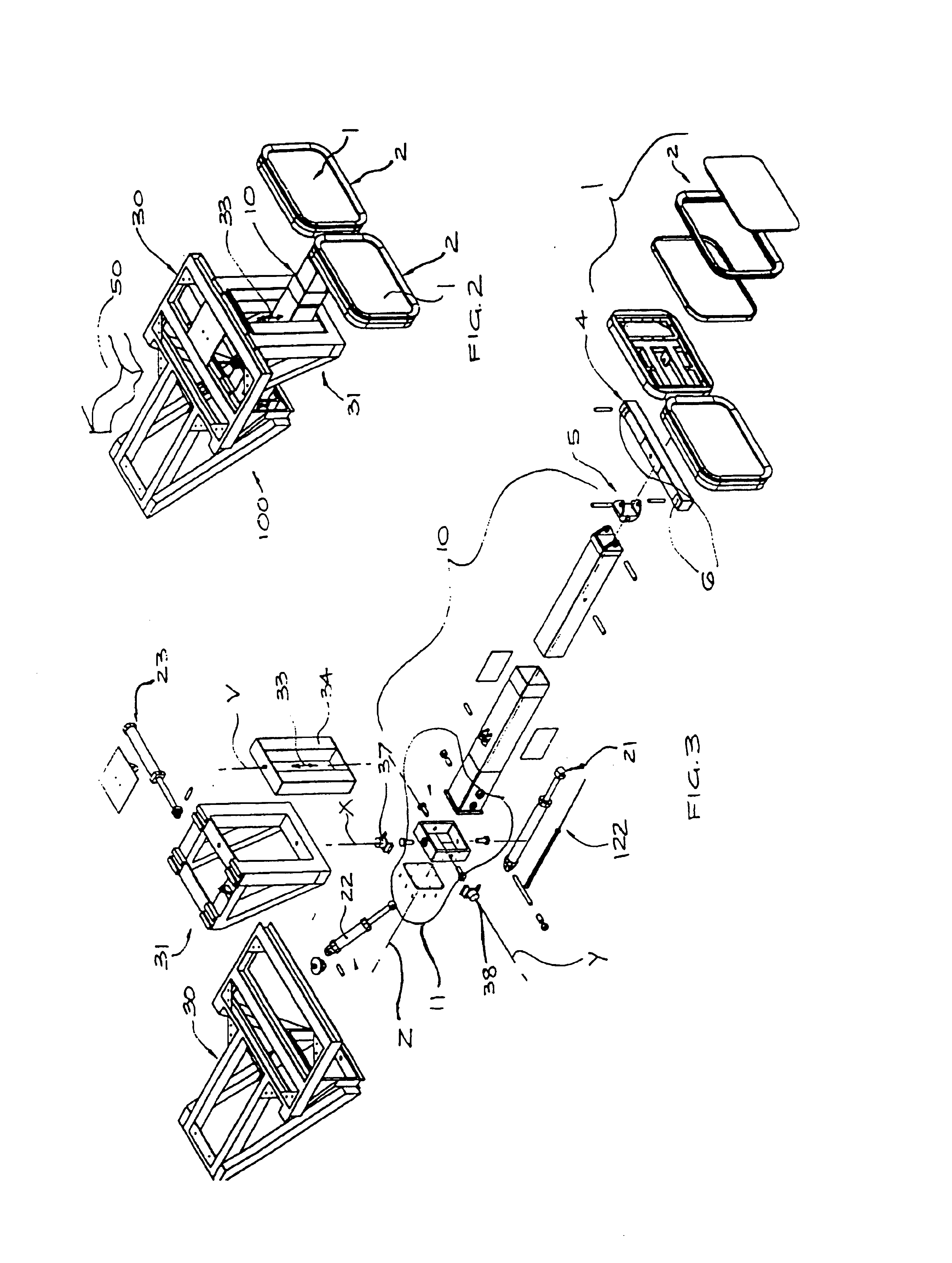
[0060]FIG. 2 illustrates this first preferred embodiment of the mooring robot 100, which includes a mounting frame 30 fixed to the dock 50. The robot arm 10 is fixed by means of the gimbal 11 (FIG. 1) to the mounting frame 30, and protrudes through a vertically extending aperture 33 in a sub-frame 31 which is slidably connected to the mounting frame 30. The sub-frame 31 ...


PUM


Abstract

A mooring robot releasably fastening a first moveable object (S) to a second nearby object. The first moveable object (S) moves in response to the application of external forces to the object (S). The robot operates to restore the first object (S) to a predetermined operating position. With the particular reference to the mooring of a vessel (S), the mooring robot has attractive attachment element(s) fixable to a ship's hull and includes a movement unit with active three-degree-of-freedom translation, for controlling the position of the attachment element(s). The movement includes a restorative means associated with each of the two degrees of translation freedom in the horizontal plane which provide a restorative force acting to return the attachment element(s) to the predetermined operating system.

Description

[0001]This application is a National Phase in the United States of PCT / NZ01 / 00026 and claims the benefit of the New Zealand Application 501395 filed Feb. 26, 2000.TECHNICAL FIELD[0002]The present invention relates generally to mooring devices for releasably securing and retaining in position a large object in relation to a nearby second large object. More particularly, the present invention relates to robotic mooring devices for controlling the mooring and departure process for vessels from a fixed or floating dock, or from another vessel.BACKGROUND ART[0003]Whilst the invention relates to a mooring device for releasably securing and retaining in position a large object in relation to a nearby second large object, it will be described with reference to mooring devices for docking and undocking a vessel. However, it will be understood that the invention is not limited solely to such example.[0004]The use of robot-like mooring devices has been proposed to reduce the labour intensity, ...

Claims


Application Information

Patent Timeline
Patent Type & Authority Patents(United States)
IPC IPC(8): B63B21/00
CPCB63B21/00B63B2021/006
Inventor HADCROFT, JOHN MACKAYMONTGOMERY, PETER JAMES
Owner CAVOTEC MOORMASTER
Why Eureka
Try Eureka