Iris diaphragm

Inactive Publication Date: 2005-06-28
WILKES IRIS
View PDF5 Cites 10 Cited by
  • Summary
  • Abstract
  • Description
  • Claims
  • Application Information

AI Technical Summary

Benefits of technology

[0009]According to the present invention an iris diaphragm comprising an annular base, an annular rotatable element and a number of leaves which can be mounted to form a variable aperture, each leaf extending between the base and element and being connected thereto in a pivotal relationship, is characterised in that

Problems solved by technology

Spot lights are commonly cumbersome in size and shape, and can be fitted with adjustable colour filters and various electronic or electric components.
This can be a problem when several independent items of equipment have to be mounted before a spot light.

Method used


Image

  • Iris diaphragm
  • Iris diaphragm
  • Iris diaphragm

Examples


Embodiment Construction

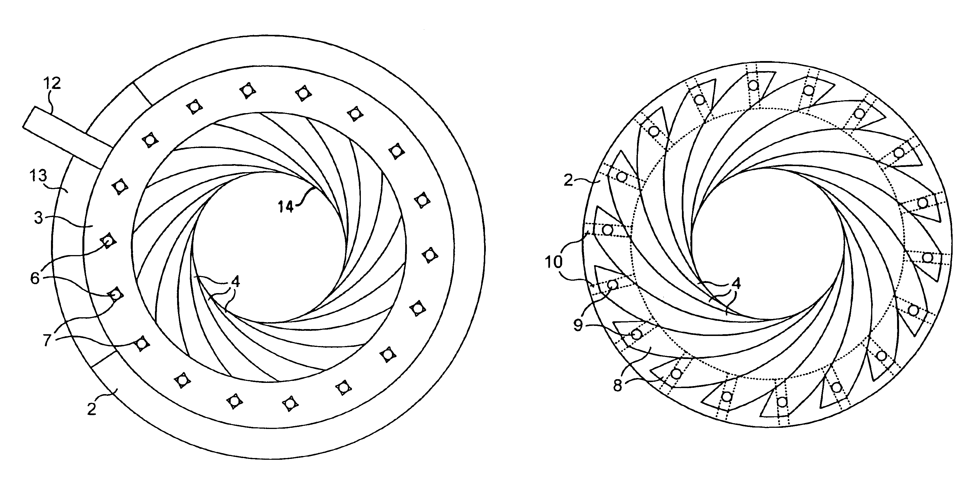
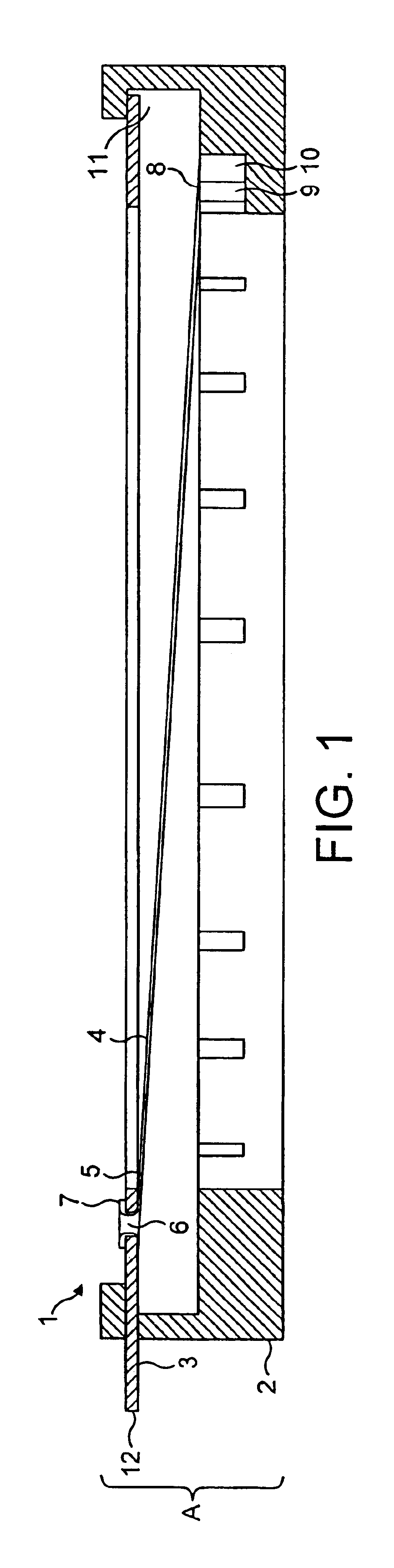
[0019]In FIG. 1 an iris diaphragm 1 comprises a base 2, a rotatable disc 3 and a number of leaves 4 (only one leaf shown in FIG. 1). A first end 5 of the leaf 4 is rotatably attached to an opening 6 provided in the disc 3, by means of a burst hole joint 7. A second end 8 of the leaf 4 is provided with a pin 9 which is positioned in a slide 10, which is provided in the base 2.

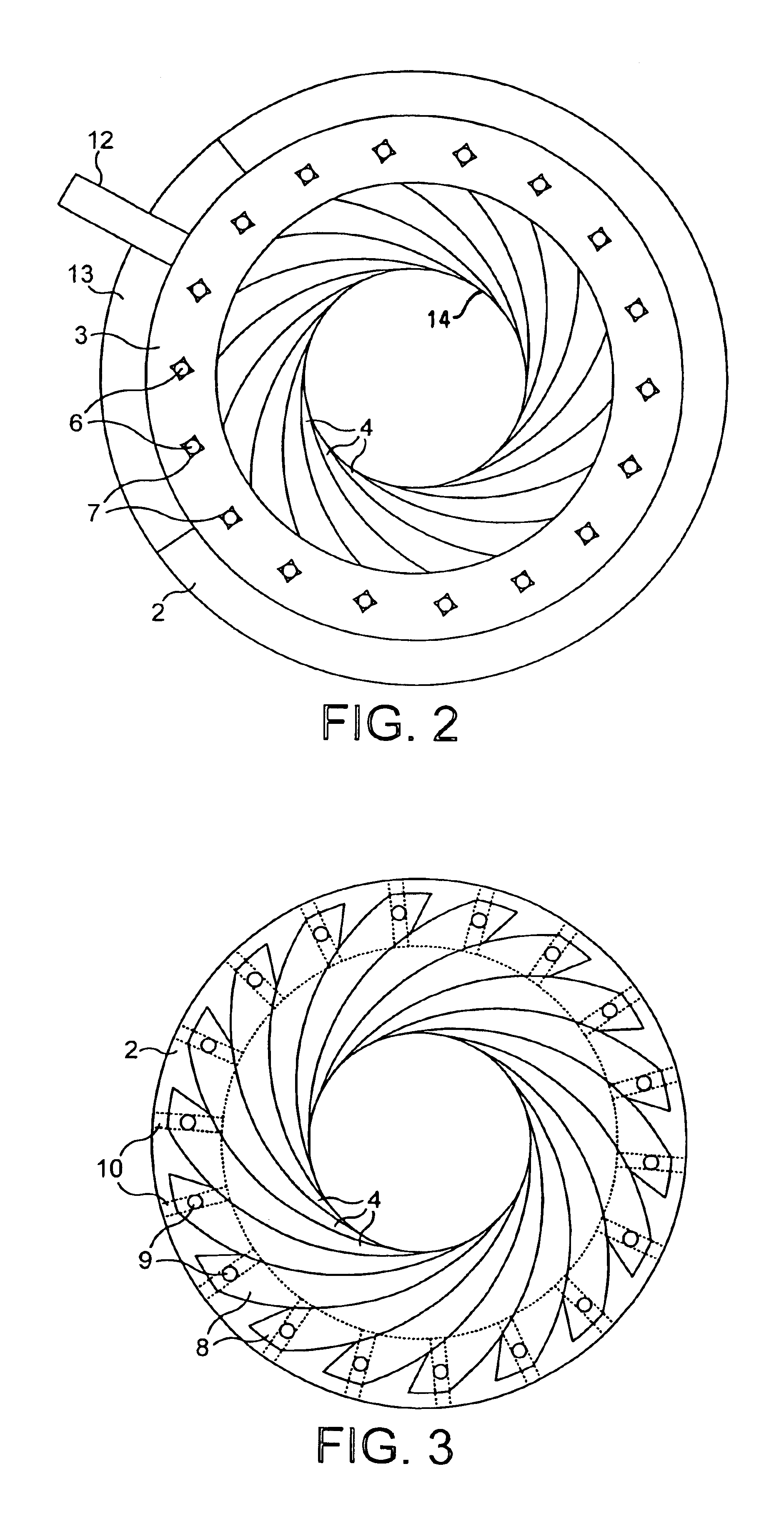
[0020]As shown in FIG. 2 the disc 3 is provided with eighteen apertures 6, one for each of the eighteen burst hole joints 7 on each of the overlapping leaves 4. Accordingly, as shown in FIG. 3 the base 2 (the outline of which is shown in broken lines) is provided with eighteen slides 10, and each leaf 4 is provided with a pin 9, which is positioned in one slide 10.

[0021]The disc 3 is positioned in a slot 11 (as shown in FIG. 1) provided in the base 2, and it is provided with an operating handle 12, positioned in a further slot 13 (as shown in FIG. 2) provided in the base 2.

[0022]When the disc 3 is rotated by the...


PUM


Abstract

An iris diaphragm comprising an annular base, an annular rotatable element and a number of leaves which can be mounted to form a variable aperture, each leaf extending between the base and element and being connected thereto in a pivotal relationship, is characterised in that a first end of each of said leaves is pivotally connected to an opening provided on the element or base by means of a burst hole joint, and a second end of each of said leaves being rotatably secured in a sliding relationship to a slide provided on the base or the element by means of a slide pin secured to the leaf.

Description

BACKGROUND OF THE INVENTION[0001]This invention relates to an iris diaphragm which is particularly, but not exclusively, for use with spot lights.[0002]An iris diaphragm comprises a number of overlapping curved leaves mounted in a circle around an aperture, which can be rotated in unison to adjust the diameter of the aperture. Iris diaphragms are commonly used with spot lights, to narrow or broaden the beam of light. They are also used to regulate the amount of light entering an optical instrument, for example a camera.[0003]An iris diaphragm comprises a base provided with an aperture, a rotatable element provided with a corresponding aperture, and a number of curved leaves, one end of which are mounted in a fixed pivotal position to one of the element or base, and the other end of which are mounted in a sliding pivotal position to the other of the element or base.[0004]The leaves are mounted at equal points around the circumference of the aperture, and are so shaped that the curve ...

Claims


Application Information

Patent Timeline
IPC IPC(8): F21V11/10F21V11/00G03B9/02G03B9/06
CPCG03B9/06F21V11/10G03B9/02
Inventor WOODS, KEITH
Owner WILKES IRIS
Why Eureka
Try Eureka