Composite needle of knitting machine

a knitting machine and needle technology, applied in the field of knitting needles, can solve the problems of preventing an accurate knitting operation, affecting the accuracy of knitting operations,

Inactive Publication Date: 2005-07-12
SHIMA SEIKI MFG LTD
View PDF11 Cites 26 Cited by
  • Summary
  • Abstract
  • Description
  • Claims
  • Application Information

AI Technical Summary

Problems solved by technology

The above-described structure in which the slider advances to allow the two blades to be branched left and right tends to cause the two blades to have therebetween adhesion and accumulation of dust such as lint particles.
Such adhesion and accumulation of dust between the two blades causes the slider to have an increased sliding resistance or causes the blade to become deformed.
Such an increased sliding resistance of...

Method used


Image

  • Composite needle of knitting machine
  • Composite needle of knitting machine
  • Composite needle of knitting machine

Examples


Embodiment Construction

[0018]Embodiments of the present invention are described with reference to the drawings.

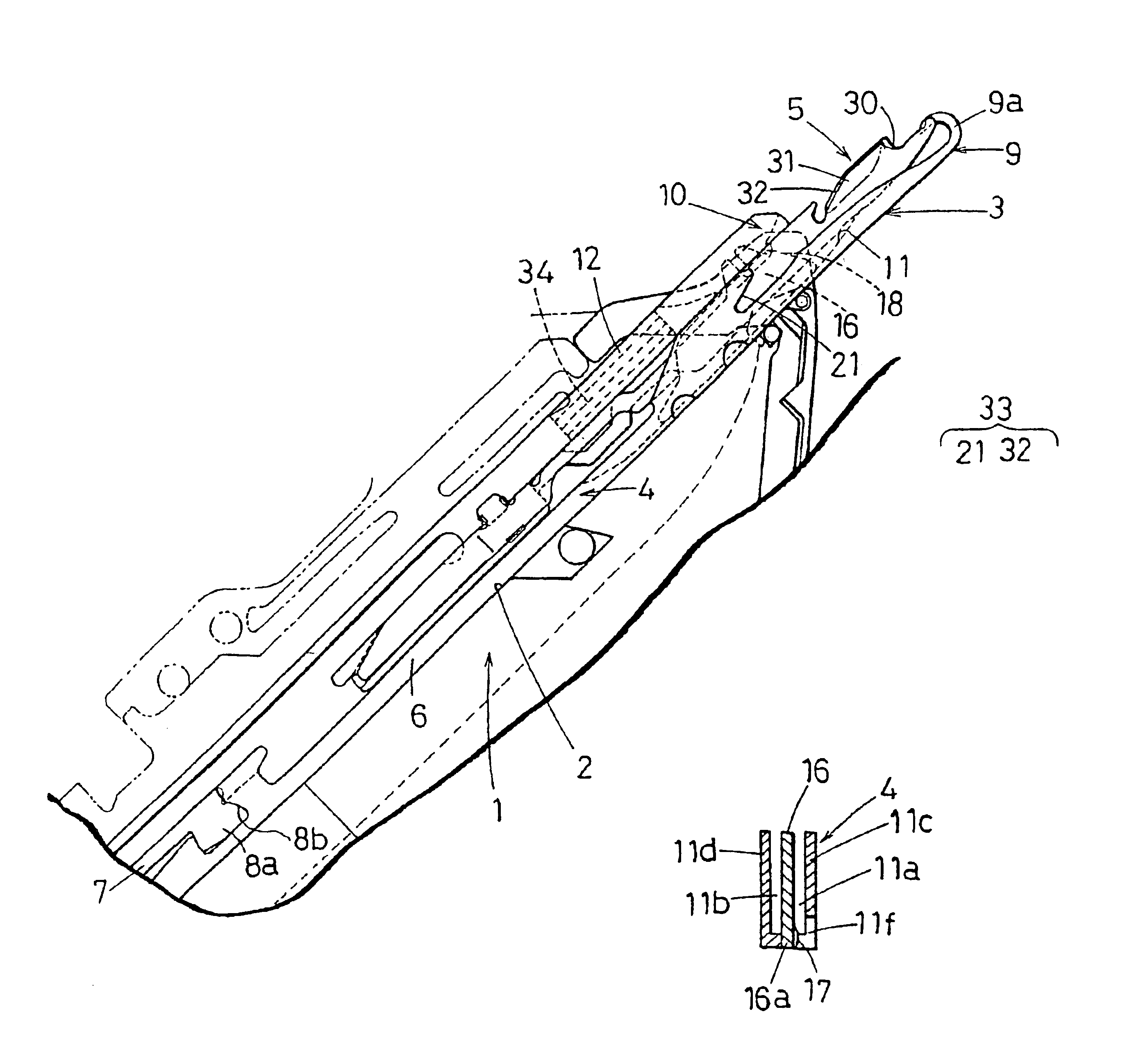
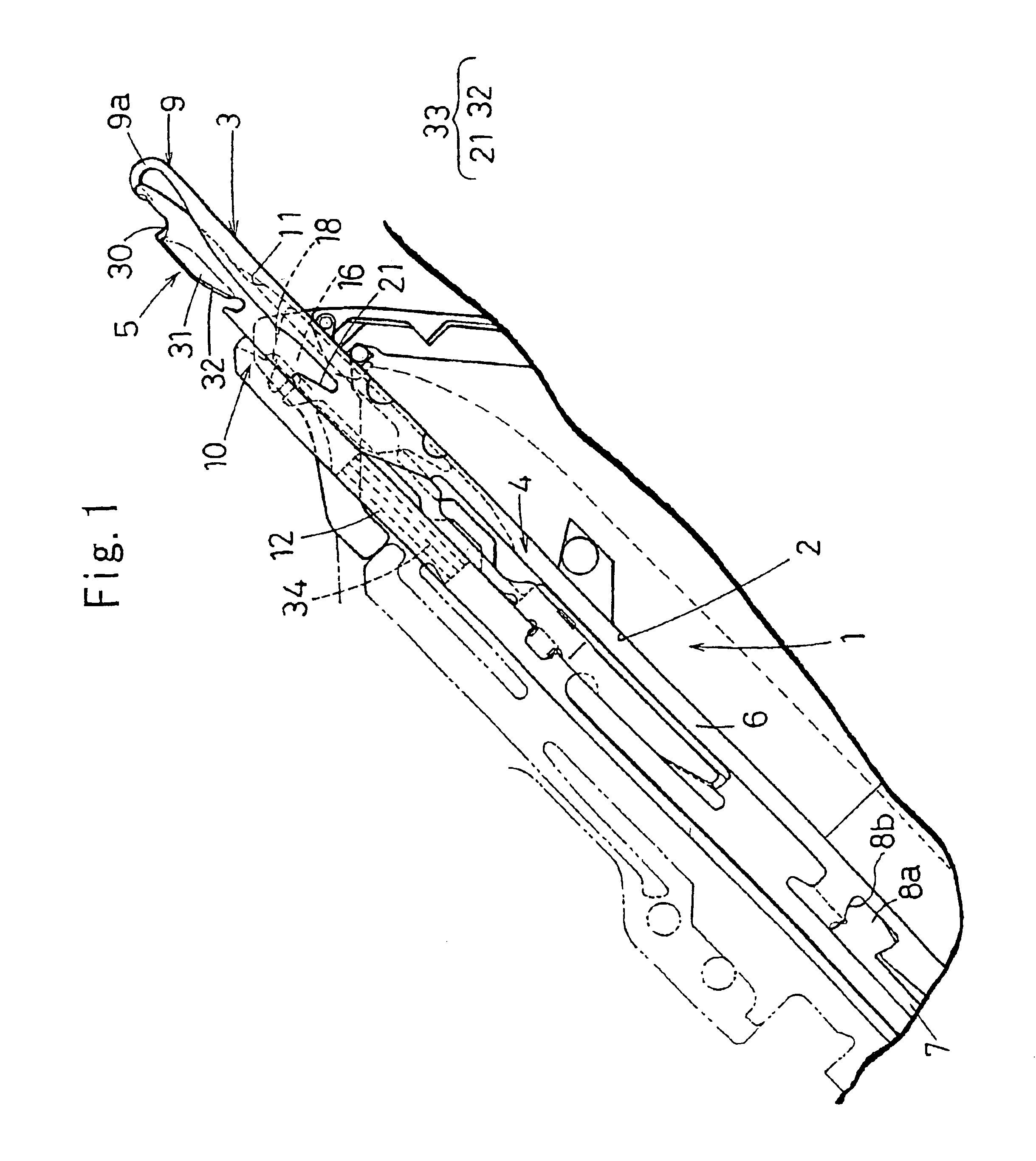
[0019]FIG. 1 illustrates a head part of a composite needle 3 attached to a needle groove 2 provided in a needle bed of a flat knitting machine.

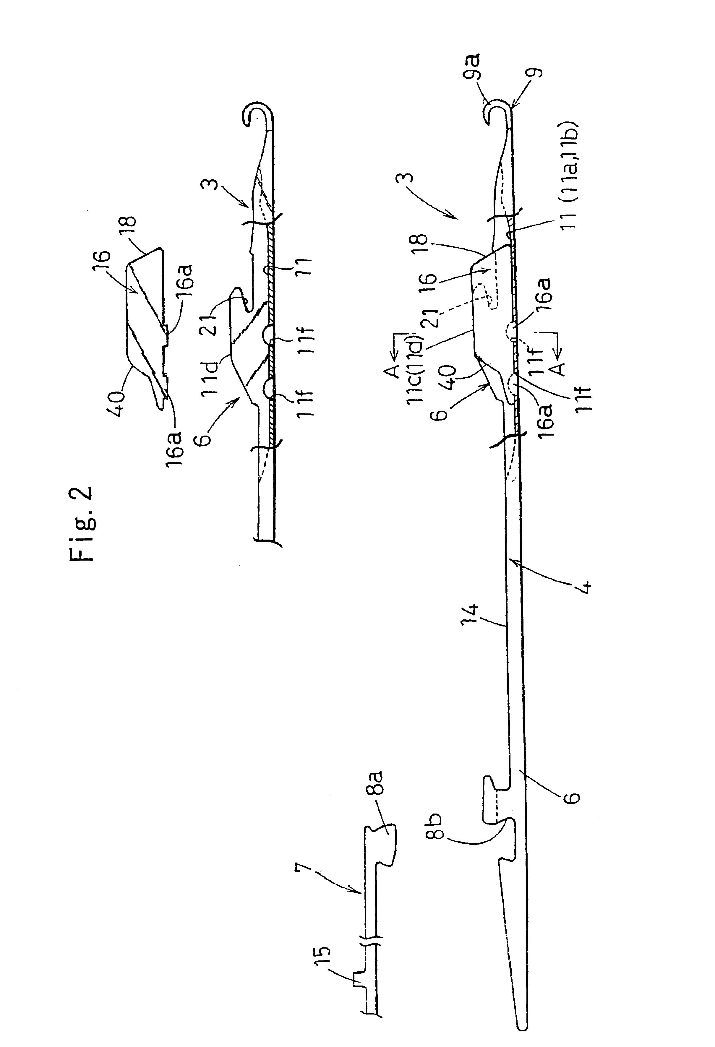
[0020]FIG. 2 is a cutaway partial side view of a needle body 4. FIG. 3 is a cross-sectional view taken along line A—A shown in FIG. 2. FIG. 4 is a side view illustrating details of parts composing a slider 5.

[0021]The composite needle 3 is composed of the needle body 4 and the slider 5. The needle body 4 consists of a hook member 6 and a jack 7 having a separate body. The hook member 6 and the jack 7 may be provided in an integrated manner, but the hook member 6 and the jack 7 in the present embodiment are integrated by engagement of an engagement section 8a and an engagement concave section 8b.

[0022]The hook member 6 includes, from a tip end side, a hook section 9; a body center section 14 for supporting a blade groove 11 for storing a blade section 10 o...


PUM


Abstract

A composite needle of a knitting machine, comprises: a needle body having at a tip end a hook; a slider formed by superposing two blades, wherein the composite needle of the knitting machine is formed such that a blade groove provided in the needle body supports the blades of the slider when the needle body and the slider can separately slide in forward and backward directions; and a dust-collecting plate that is seperately formed from the needle body and that extends, when viewed from a side, from the blade groove of the needle body in an upward direction and to a hook side of the needle such that the dust-collecting plate is provided at a tip end of the slider proximate to the hook.

Description

TECHNICAL FIELD[0001]The present invention relates to a knitting needle used in a knitting machine. In particular, the present invention relates to a composite needle that has a needle body having at a tip end a hook, and that has at the tip end tongues structured to have relative displacement with respect to a needle body section. The tongues work in cooperation with the hook to close and open the hook so that dust adhered to and accumulated in the composite needle can be removed.BACKGROUND ART[0002]Japanese Patent Publication No. 2946323 proposed by the present applicant discloses a known needle body having a tip end a hook and a slider, in which the needle body and slider have relative displacement to allow the hook to be closed and opened.[0003]This composite needle has a slider formed by superimposing two blades. The blades have a thickness that is thinner than a groove width of a blade storage groove provided in the needle body. This provides a gap between the blades and the g...

Claims


Application Information

Patent Timeline
IPC IPC(8): D04B35/32D04B35/00D04B35/06
CPCD04B35/06D04B35/32
Inventor MORITA, TOSHIAKINAKAMORI, TOSHINORI
Owner SHIMA SEIKI MFG LTD
Why Eureka
Try Eureka