Low insertion effort U-base retainer

Inactive Publication Date: 2005-08-16
NEWFREY
View PDF57 Cites 54 Cited by
  • Summary
  • Abstract
  • Description
  • Claims
  • Application Information

AI Technical Summary

Problems solved by technology

Due to slight misalignments, which can occur between the fasteners and their corresponding mo

Method used


Image

  • Low insertion effort U-base retainer
  • Low insertion effort U-base retainer
  • Low insertion effort U-base retainer

Examples


Embodiment Construction

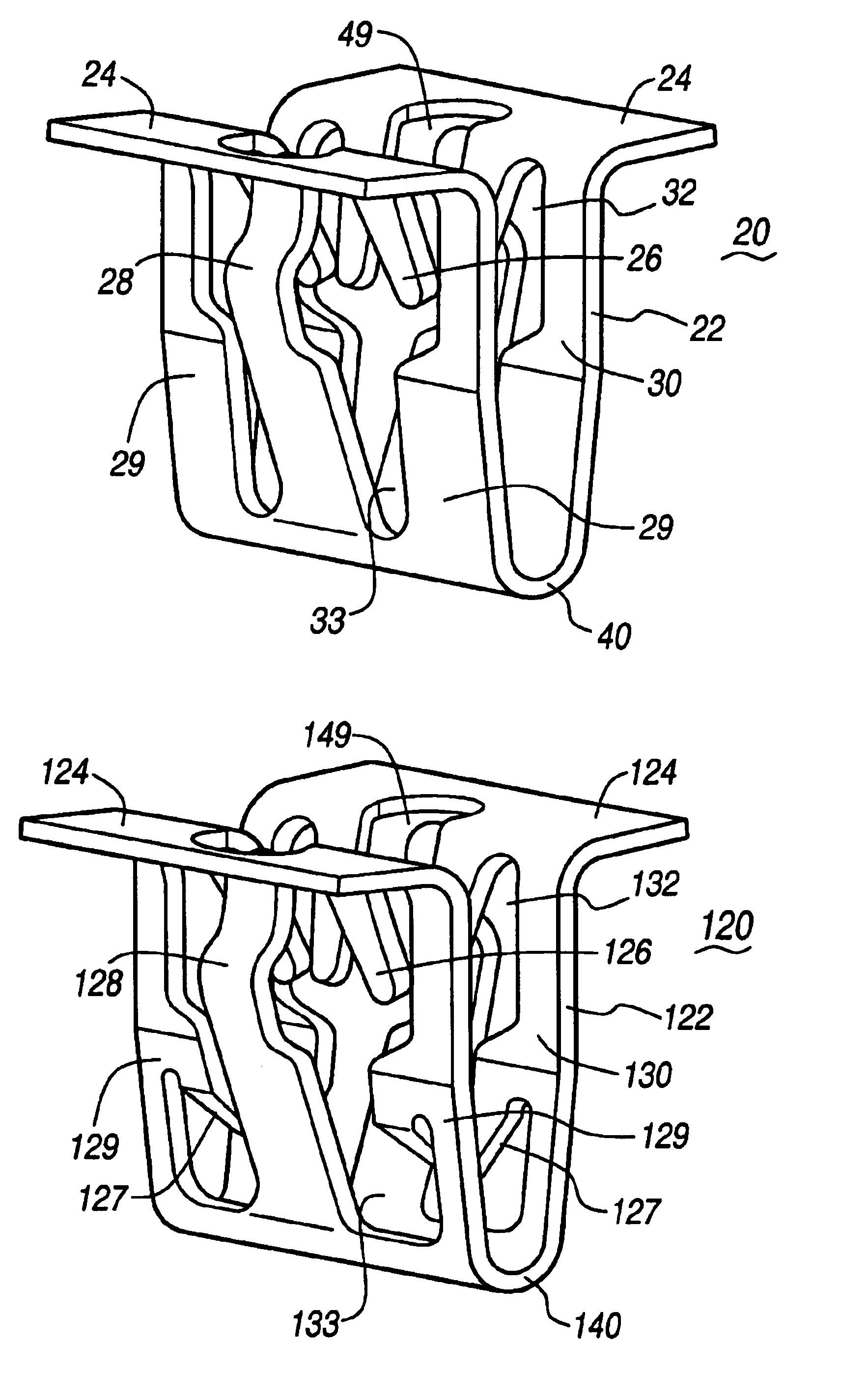
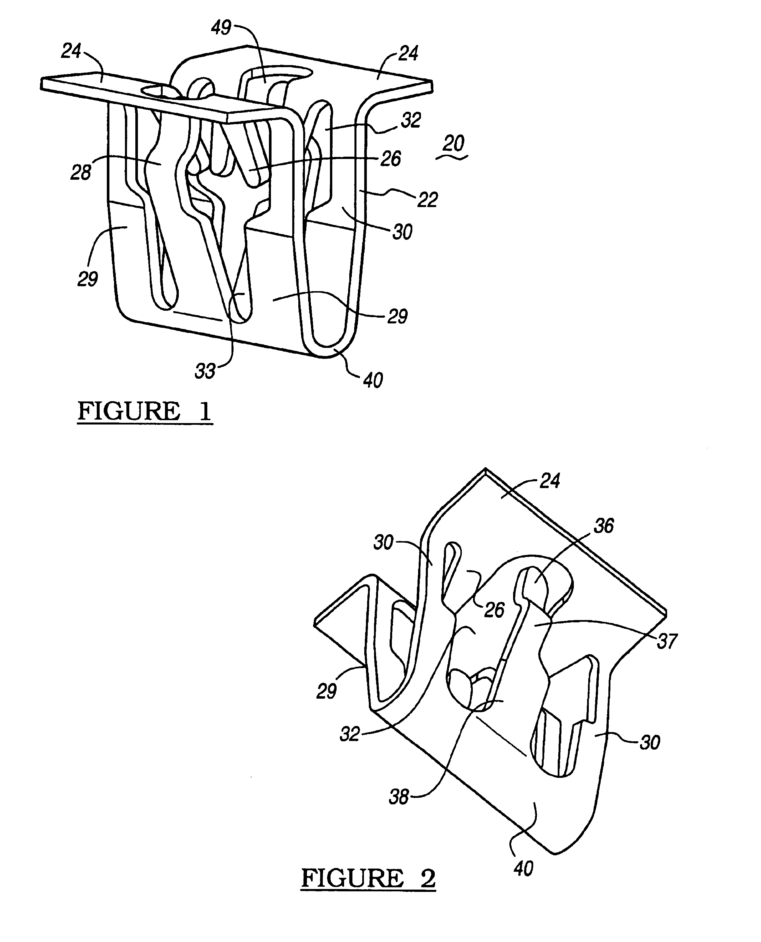
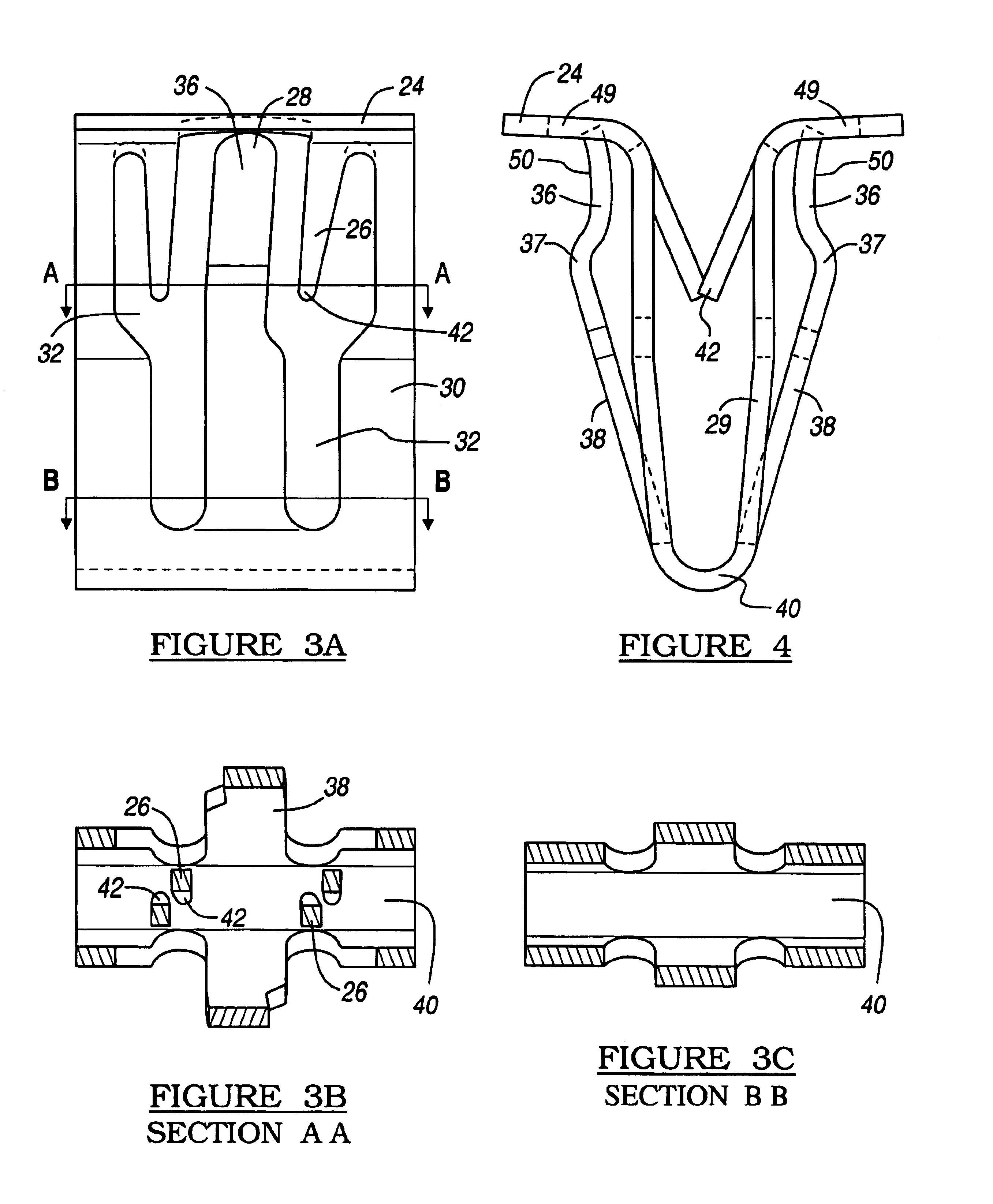
[0037]Referring to FIGS. 1 through 8, a generally U-shaped fastener 20 in accordance with the present invention is disclosed. The generally U-shaped fastener 20 is defined by a body portion 22 and a pair of top flanges 24. Integral with the top flanges 24 are two pair of finger members 26 which are used to couple the generally U-shaped fastener 20 to a mounting flange (shown in FIG. 11). Additionally, the body portion 22 has a pair of abutting flanges 28 which generally lie outside side members 29 and 30 of the body portion 22. The side members, which are coupled by a bottom curved member 29 and 30, define a pair of apertures 32 and 33, which allow for the inward compression of the abutting flanges 28.

[0038]Generally, the abutting flanges 28 are defined by three portions. The first portion 36 is defined by an exterior concave engaging surface 50. The second portion 37, which acts as a transition to the third portion 38, is defined by a convex surface. The third portion 38 functions ...


PUM


Abstract

A resilient clip for engaging a structure and having a body portion (22) with a pair of top flanges (24), a pair of fastening fingers (26) and a pair of abutting coupling flanges (28). Each of the fastening fingers (26) are coupled to the body portion (22) that is coupled to an associated top flange (24). Each of the abutting flanges (26) has a concave surface, which engages the mounting structure. The fastening finger (26) portions are configured to engage a first side of a mounting flange on an interior trim component.

Description

CROSS-REFERENCES TO RELATED APPLICATION[0001]This application is a continuation of International Application No. PCT / US02 / 06753 Mar. 4, 2002 and published on Sep. 12, 2002 under International Publication No. WO 02 / 070905, which claims priority to Provisional U.S. Patent Application Ser. No. 60 / 272,992 which was filed Mar. 2, 2001.TECHNICAL FIELD[0002]The present invention relates generally to resilient clip fasteners and more particularly to a resilient clip fastener that employs a particular surface geometry to secure the body portion of the resilient clip to a structure. More specifically, the present invention relates to a resilient clip fastener having a construction that utilizes abutment flanges to permit the clip to be inserted into an aperture with a relatively low insertion force while resisting relatively high withdrawal forces. The invention also relates to a resilient clip fastener having a construction that accounts in several manners for part-to-part variation between ...

Claims


Application Information

Patent Timeline
IPC IPC(8): B60R13/02F16B5/12B60R13/04F16B5/06B60R11/00B60J5/00E04F19/02F16B19/00F16B21/06
CPCB60R13/0206B60R13/04F16B5/065F16B5/125F16B5/0657B60R2011/0021F16B5/0614Y10T24/304Y10T24/306Y10T24/44026Y10T24/307Y10T24/30
Inventor OSTERLAND, ROBERT WILLIAMSSLOBODECKI, JEFF A.
Owner NEWFREY
Why Eureka
Try Eureka