Method for selectively treating two producing intervals in a single trip

a technology of selective treatment and production interval, which is applied in the direction of sealing/packing, fluid removal, borehole/well accessories, etc., can solve the problems of preventing the placement of sufficient gravel (a) below the bridge in top-to-bottom packing operations or (b) above the bridge in bottom-to-top packing operations

Inactive Publication Date: 2005-08-23
BAKER HUGHES INC
View PDF27 Cites 10 Cited by
  • Summary
  • Abstract
  • Description
  • Claims
  • Application Information

AI Technical Summary

Benefits of technology

[0009]A method is disclosed that allows for sequential treatment of two zones in a single trip while isolating the zones. A fluid loss valve prevents the column of fluid in the tubing from flowing into the lower formation until activated. Zone isolation is accomplished by manipulation of a port on a wash pipe attached to the crossover assembly.

Problems solved by technology

As is well known in the art, these particulates routinely cause a variety of problems and must be controlled in order for production to be economical.
One major problem that occurs in gravel-packing single zones, particularly where they are long or inclined, arises from the difficulty in distributing the gravel over the entire completion interval, i.e., completely packing the entire length of the well annulus around the screen.
This poor distribution of gravel (i.e., incomplete packing of the interval) is often caused by the carrier fluid in the gravel slurry being lost into the more permeable portions of the formation, which, in turn, causes the gravel to form “sand bridges” in the annulus before all the gravel has been placed.
Such bridges block further flow of slurry through the annulus, which prevents the placement of sufficient gravel (a) below the bridge in top-to-bottom packing operations or (b) above the bridge in bottom-to-top packing operations.
One of the problems with the alternate path design is the relatively small size of the passages through them.
These tubes are also subject to being crimped or otherwise damaged during the installation of the screen.
This type of design substantially increases the cost of the screen over commercially available screens.
While such designs can be of some benefit in a bridging situation, they present difficulties in attempting to treat and gravel-pack zones which are fairly close together.
Many times zones are so close together that traditional isolation devices between the zones cannot be practically employed because the spacing is too short.
The limitation of that method was that the two zones had to be treated simultaneously.
This caused problems if the nature of the adjacent formations necessitated a different treatment program.
The isolation of the zones after completion was also less than ideal.

Method used


Image

  • Method for selectively treating two producing intervals in a single trip
  • Method for selectively treating two producing intervals in a single trip
  • Method for selectively treating two producing intervals in a single trip

Examples


Embodiment Construction

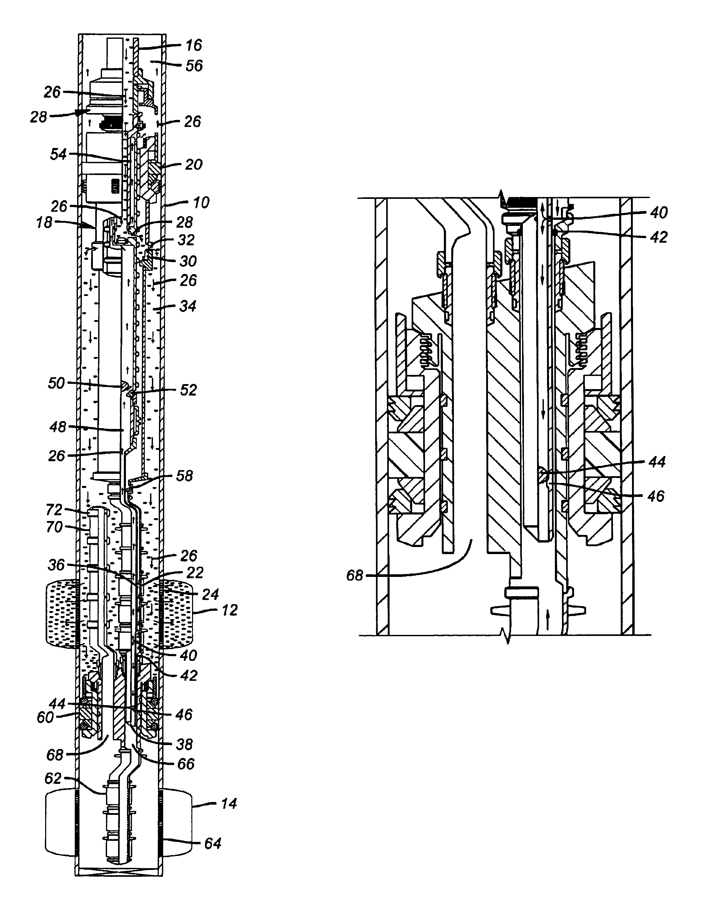
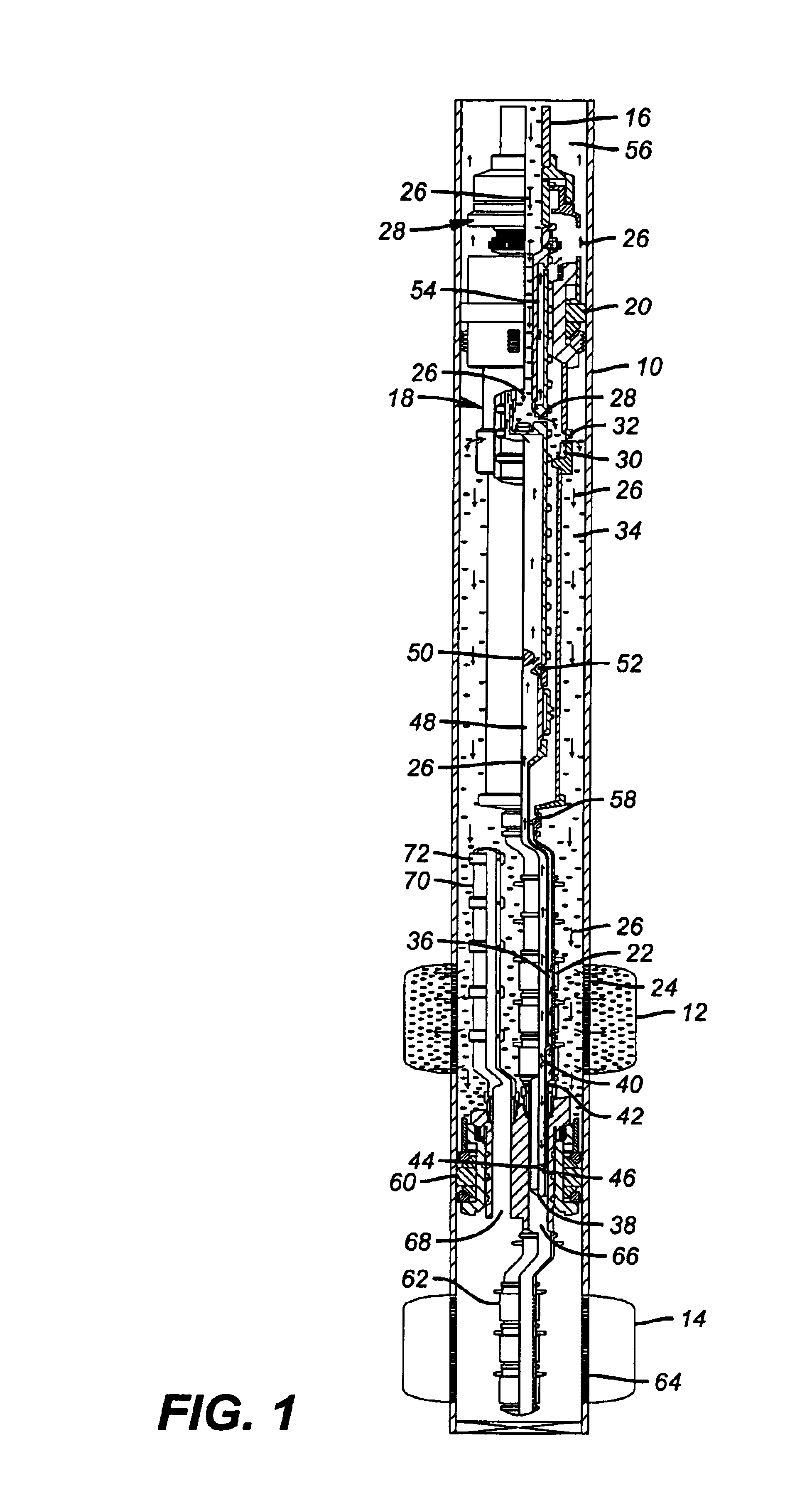
[0016]FIG. 1 shows a wellbore 10 and zones 12 and 14 to be treated. The preferred embodiment illustrates the method for two zones but those skilled in the art will appreciate that additional zones can be treated in a single trip with duplication of the equipment shown for doing two zones in one trip, as will be explained below. A tubular string 16 is used to run in a known crossover tool 18, which is movable with respect to packer 20 after it is set. In FIG. 1, the packer 20 is shown in the set position and the crossover is set up to circulate to deposit gravel outside of screen 22 and adjacent the perforations 24 of zone 12. Arrows 26 show the gravel and fluid mixture coming from the surface through the string 16 and going through the packer 20. The gravel and fluid stream indicated by arrows 26 goes through crossover 18 and through ports 28 in the crossover tool 18. Sliding sleeve valve 30 is left in the open position during run in so that the ports 32 are open for the gravel and ...


PUM


Abstract

A method is disclosed that allows for sequential treatment of two zones in a single trip while isolating the zones. A fluid loss valve prevents the column of fluid in the tubing from flowing into the lower formation until activated. Zone isolation is accomplished by manipulation of a port on a wash pipe attached to the crossover assembly.

Description

PRIORITY INFORMATION[0001]This application claims the benefit of U.S. Provisional Application No. 60 / 390,634 on Jun. 21, 2002.FIELD OF THE INVENTION[0002]The field of this invention relates to techniques and equipment to gravel-pack and treat closely spaced zones and more particularly in applications where some degree of isolation is desired between the zones for accommodating different treatment plans.BACKGROUND OF THE INVENTION[0003]In producing hydrocarbons or the like from loose or unconsolidated and / or fractured formations, it is not uncommon to produce large volumes of particulate material along with the formation fluids. As is well known in the art, these particulates routinely cause a variety of problems and must be controlled in order for production to be economical. A popular technique used for controlling the production of particulates (e.g., sand) from a well is one which is commonly known as “gravel-packing.”[0004]In a typical gravel-packed completion, a screen is lower...

Claims


Application Information

Patent Timeline
Patent Type & Authority Patents(United States)
IPC IPC(8): E21B43/00E21B43/02E21B43/04E21B43/14
CPCE21B43/045E21B43/14
Inventor BAYNE, CHRISTIAN F.BAYCROFT, PERRY D.
Owner BAKER HUGHES INC
Why Eureka
Try Eureka