
Combined tension and back stop function for seating unit

a seat and back stop technology, applied in the field of seat units, can solve problems such as unfriendly to the environment and considerable effor

Inactive Publication Date: 2005-08-23
STEELCASE INC
View PDF27 Cites 74 Cited by
  • Summary
  • Abstract
  • Description
  • Claims
  • Application Information

AI Technical Summary

Benefits of technology

The present invention relates to a seating unit with a back that can move between upright and reclined positions. The unit includes a control mechanism for synchronizing the movement of the back. The control mechanism includes a housing, a biasing supporting force for the back during recline, and a booster spring mechanism for increasing the supporting force. The booster spring mechanism is operably connected to the back for rotation during recline. The seating unit also includes an energy mechanism for biasing the back toward the upright position, and a first adjustment mechanism and a second mechanism for selectively operating both mechanisms. The invention also includes a covering for the flexible supports and a lumber device for supplementing the supporting force in a selected location. Additionally, the invention includes a headrest mount for distributing stress across the top frame section and a clamping arrangement for the headrest adjustment.

Problems solved by technology

This takes considerable effort, even if a mechanical advantage is provided, since the springs are substantial and there is significant energy input required to compress the spring.
Even adjustments that decompress the spring require effort to overcome frictional forces that prevent unexpected decompression.
Still further, once the proper control is selected, the user still has to figure out which way to adjust the control to achieve the desired effect.
Expanded thermoset foam products are usually classified as not recyclable, and further they are generally considered to be unfriendly to the environment as compared to steel, remeltable thermoplastic, and more natural materials.

Method used


Image

  • Combined tension and back stop function for seating unit
  • Combined tension and back stop function for seating unit
  • Combined tension and back stop function for seating unit

Examples


Embodiment Construction

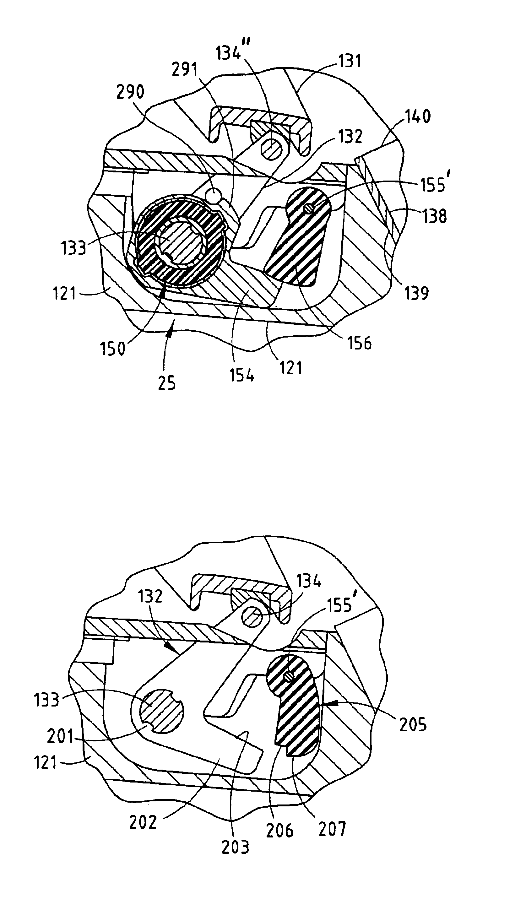
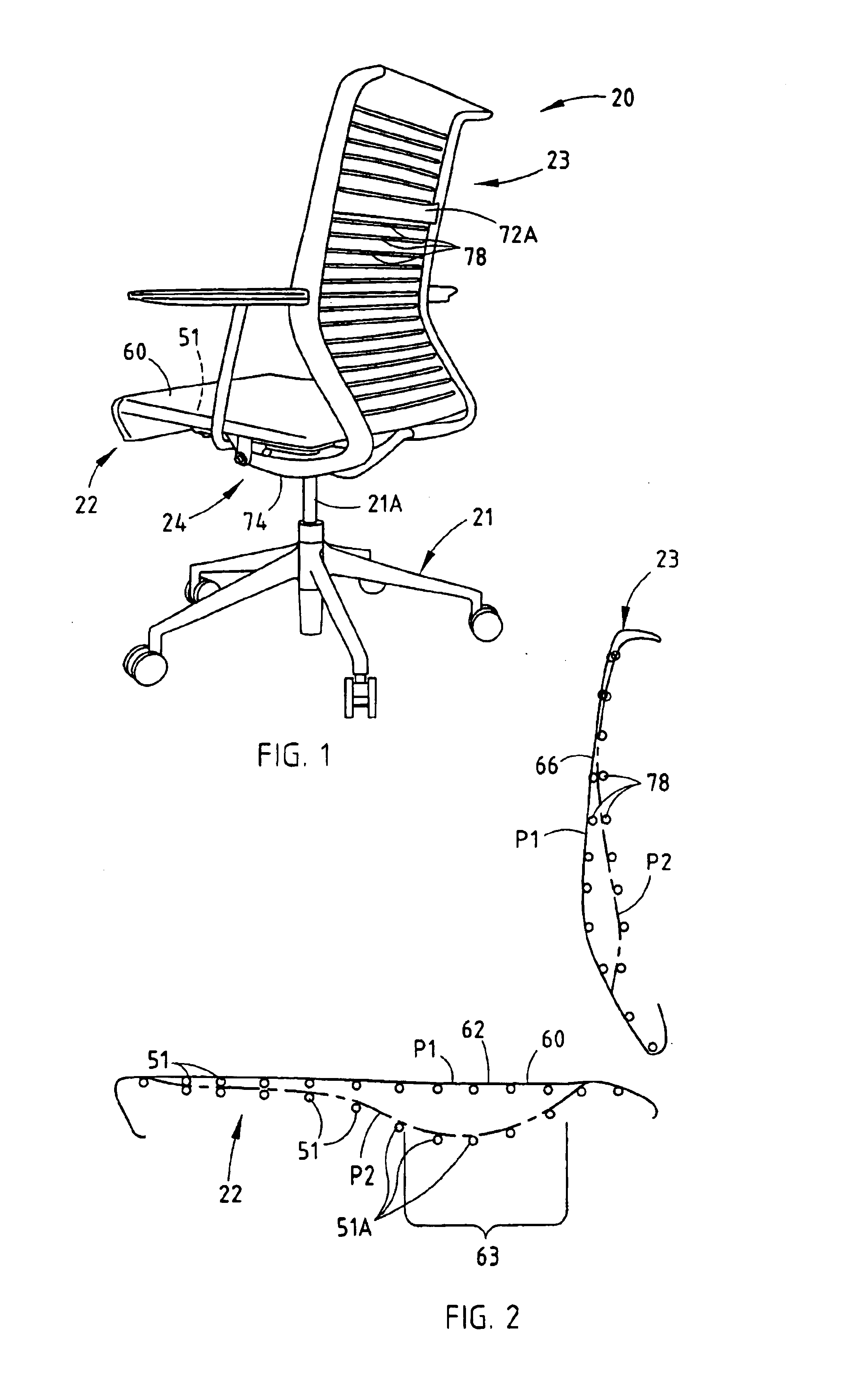
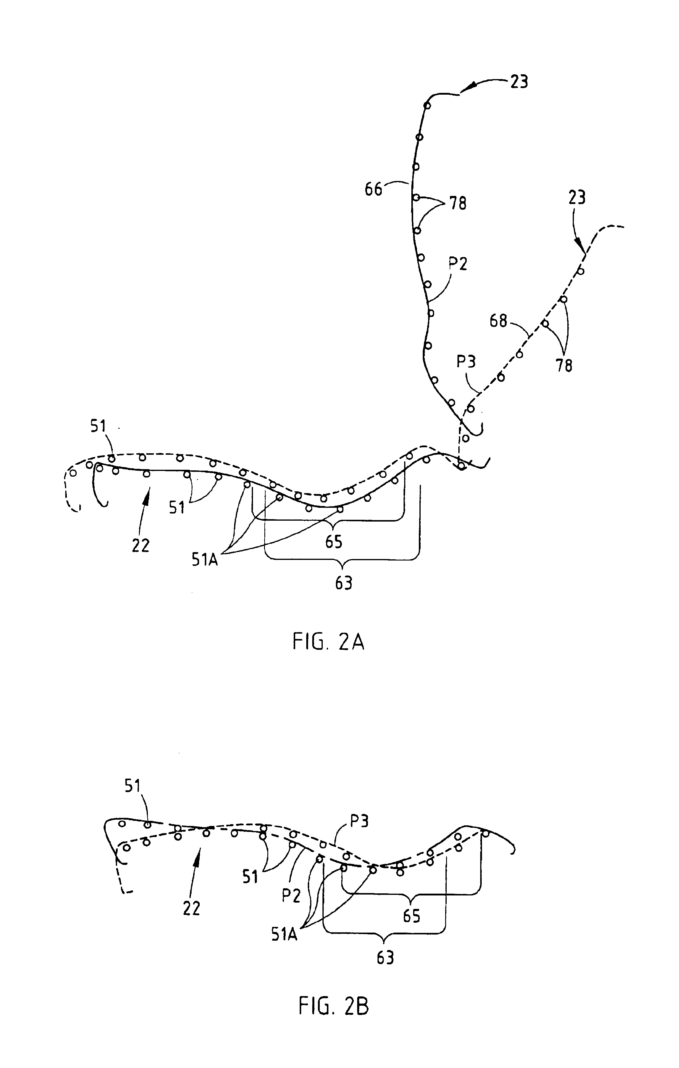
[0080]A chair 20 (FIG. 1) embodying the present invention includes a base 21, a seat 22, and a back 23, with the seat 22 and back 23 being operably supported on the base 21 by an underseat control mechanism 24 for synchronous movement upon recline of the back 23. Upon recline, the control mechanism 24 moves and lifts the seat 22 upwardly and forwardly, such that the back 23 (and the seated user) is automatically provided with a weight-activated back-supporting force upon recline. Advantageously, heavier-weight seated users receive greater back-supporting force, thus eliminating (or at least reducing) the need for them to adjust a tension device for back support when reclining in the chair. The seat 22 (and also the back 23) includes a highly comfortable support surface formed by a locally-compliant support structure (hereafter called “a comfort surface”) that adjusts to the changing shape and ergonomic support needs of the seated user, both when in an upright position and in a recli...


PUM


Abstract

A seating unit includes a base, a seat, a back, and a control operably supporting the seat and the back on the base for movement between upright and recline positions. The control includes a spring providing a biasing supporting force to the back during recline, and further includes a booster mechanism for increasing the supporting force, and still further includes a stop member and a selector device for activating and deactivating the booster mechanism. The selector device is easily movable with a low effort that is independent from friction generated by internal components of the booster mechanism. The stop member is linearly slidably mounted atop a control housing for selectively engaging the booster mechanism and the link for movement between a disengaged position, a booster-engaged position, a partial-recline position, and a recline-prevented position.

Description

CROSS REFERENCE TO RELATED APPLICATIONS[0001]This application is a continuation-in-part of co-assigned co-invented application Ser. No. 10 / 455,076, filed Jun. 5, 2003, entitled COMBINED TENSION AND BACK STOP FUNCTION FOR SEATING UNIT, the entire contents of which are incorporated herein in their entirety. This application is further related to an application Ser. No. 10 / 455,487, filed on Jun. 5, 2003, entitled SEATING WITH COMFORT SURFACE, and also to an application Ser. No. 10 / 455,503, filed Jun. 5, 2003, entitled CONTROL MECHANISM FOR SEATING UNIT, and also to an application Ser. No. 10 / 241,955, filed Sep. 12, 2002 entitled “SEATING UNIT WITH MOTION CONTROL”, the entire contents of each of which are also incorporated herein by reference.BACKGROUND[0002]The present invention relates to a seating unit having an adjustable back tension function and an adjustable back stop function.[0003]Comfort, simplicity, and adjustability continue to be highly-demanded features in seating. Specifi...

Claims


Application Information

Patent Timeline
Patent Type & Authority Patents(United States)
IPC IPC(8): A47C1/031A47C1/032A47C1/036A47C3/025A47C1/0355A47C3/026A47C7/28A47C7/38A47C7/44
CPCA47C1/023A47C1/03238A47C1/03255A47C1/03261A47C31/04A47C7/28A47C7/38A47C7/46A47C1/03277A47C1/03294A47C1/03274A47C1/024A47C1/032A47C1/02A47C7/14
Inventor BEDFORD, ADAM C.BATTEY, ROBERT J.BODNAR, DAVID A.HADLEY, JONATHAN B.HALL, JEFFREY A.HEIDMANN, KURT R.JOHNSON, ERICKARSTEN, GARY LEEPETERSON, GORDON J.
Owner STEELCASE INC
Learn More