Bandgap reference circuit

a reference circuit and band gap technology, applied in the field of reference circuits, can solve problems such as difficulties in generating reference voltage using traditional designs

Inactive Publication Date: 2005-08-23
MICRON TECH INC
View PDF46 Cites 59 Cited by
  • Summary
  • Abstract
  • Description
  • Claims
  • Application Information

AI Technical Summary

Problems solved by technology

However, in devices where a reduced supply voltage is preferable, generating the reference voltage using traditional designs may encounter difficulty.

Method used


Image

  • Bandgap reference circuit
  • Bandgap reference circuit
  • Bandgap reference circuit

Examples


Embodiment Construction

[0017]The following description and the drawings illustrate specific embodiments of the invention sufficiently to enable those skilled in the art to practice the invention. Other embodiments may incorporate structural, logical, electrical, process, and other changes. In the drawings, like numerals describe substantially similar components throughout the several views. Examples merely typify possible variations. Portions and features of some embodiments may be included in or substituted for those of others. The scope of the invention encompasses the full ambit of the claims and all available equivalents.

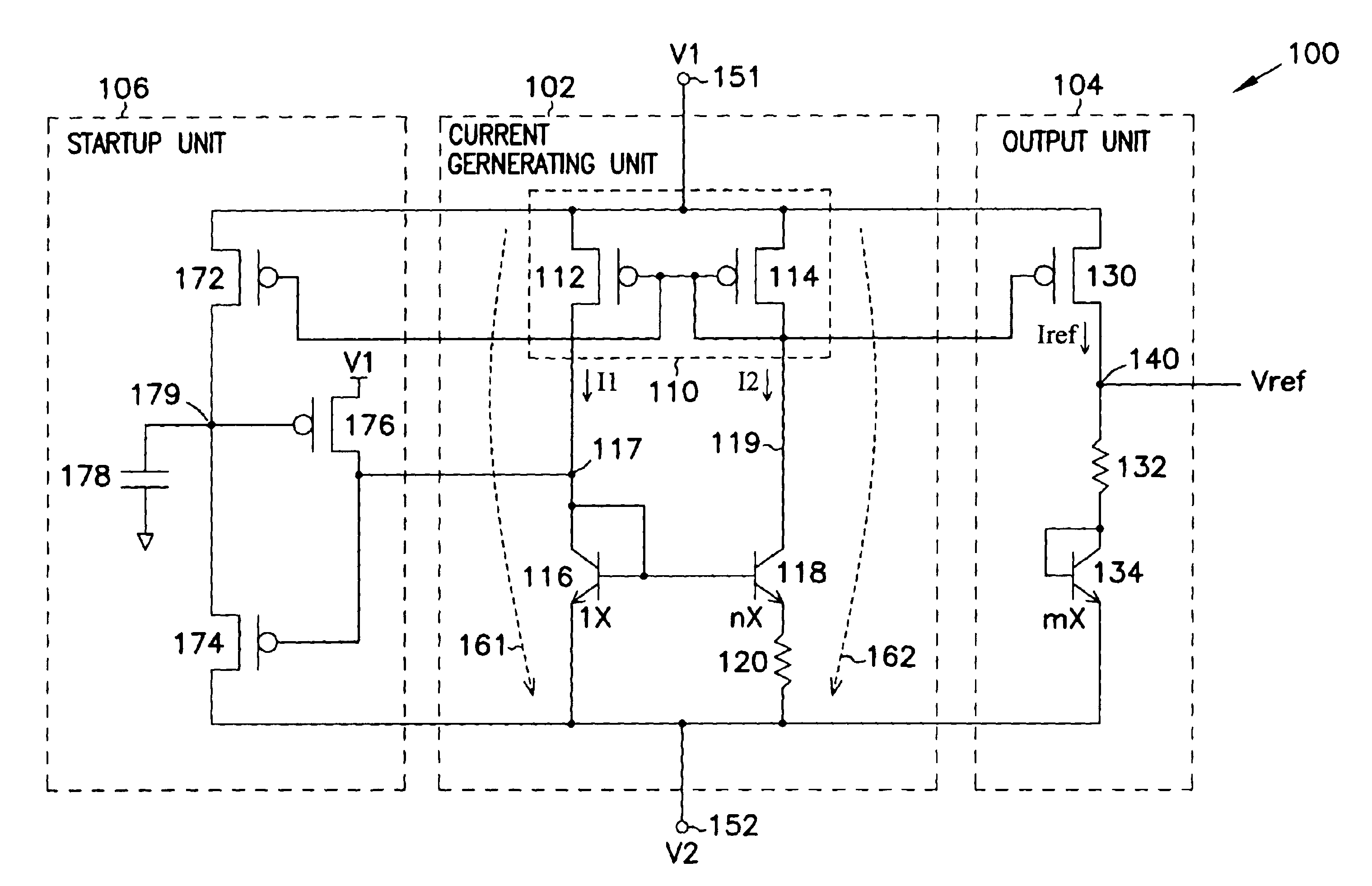
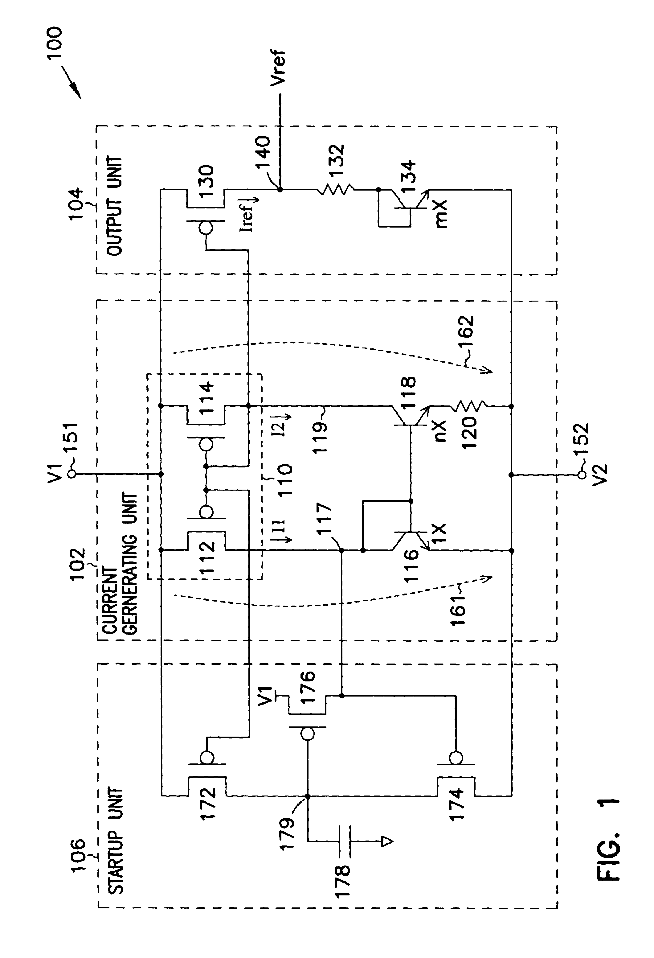
[0018]FIG. 1 shows a reference circuit according to an embodiment of the invention. Reference circuit 100 includes a current generating unit 102, an output unit 104, and a startup unit 106. Unit 102 generates currents I1 and I2 (generated currents). Output unit 104 produces a current Iref (reference current or output current) based on I1 and I2 and produces a voltage Vref (reference v...


PUM


Abstract

A reference circuit generates a reference voltage from a supply voltage. The reference circuit includes a current generating unit for generating generated currents. An output unit of the reference circuit generates the reference voltage based on the generated currents. A startup unit of the reference circuit allows the reference voltage to switch between different voltages levels in different modes.

Description

FIELD[0001]The present invention relates generally to reference circuits, and more particularly to reference circuits that provide substantially constant signals.BACKGROUND[0002]Many electrical devices have a reference circuit for generating a reference signal based on an external source for internal use. The external source is often a supply voltage. The reference signal may represent either a reference current or a reference voltage. The reference circuit is usually designed such that the reference signal has a constant level over variations in the supply voltage, over a range of temperature, and over manufacturing process variations.[0003]In most devices, the supply voltage is sufficient such that designing the reference circuit faces little problem. However, in devices where a reduced supply voltage is preferable, generating the reference voltage using traditional designs may encounter difficulty.SUMMARY OF THE INVENTION[0004]The present invention provides techniques to generate...

Claims


Application Information

Patent Timeline
Patent Type & Authority Patents(United States)
IPC IPC(8): G05F1/10H03K17/687G05F3/30
CPCG05F3/30
Inventor KOELLING, JEFFREY
Owner MICRON TECH INC
Why Eureka
Try Eureka