Bicycle carrier

Inactive Publication Date: 2005-09-06
WATERMARK PADDLESPORTS
View PDF83 Cites 47 Cited by
  • Summary
  • Abstract
  • Description
  • Claims
  • Application Information

AI Technical Summary

Problems solved by technology

One limitation of this variation is that the rear wheel must be substantially centered over the crossbar to avoid creating excess torque on the short wheel tray and/or crossbar.
This limitation can be a problem where the crossbars cannot

Method used


Image

  • Bicycle carrier
  • Bicycle carrier
  • Bicycle carrier

Examples


Embodiment Construction

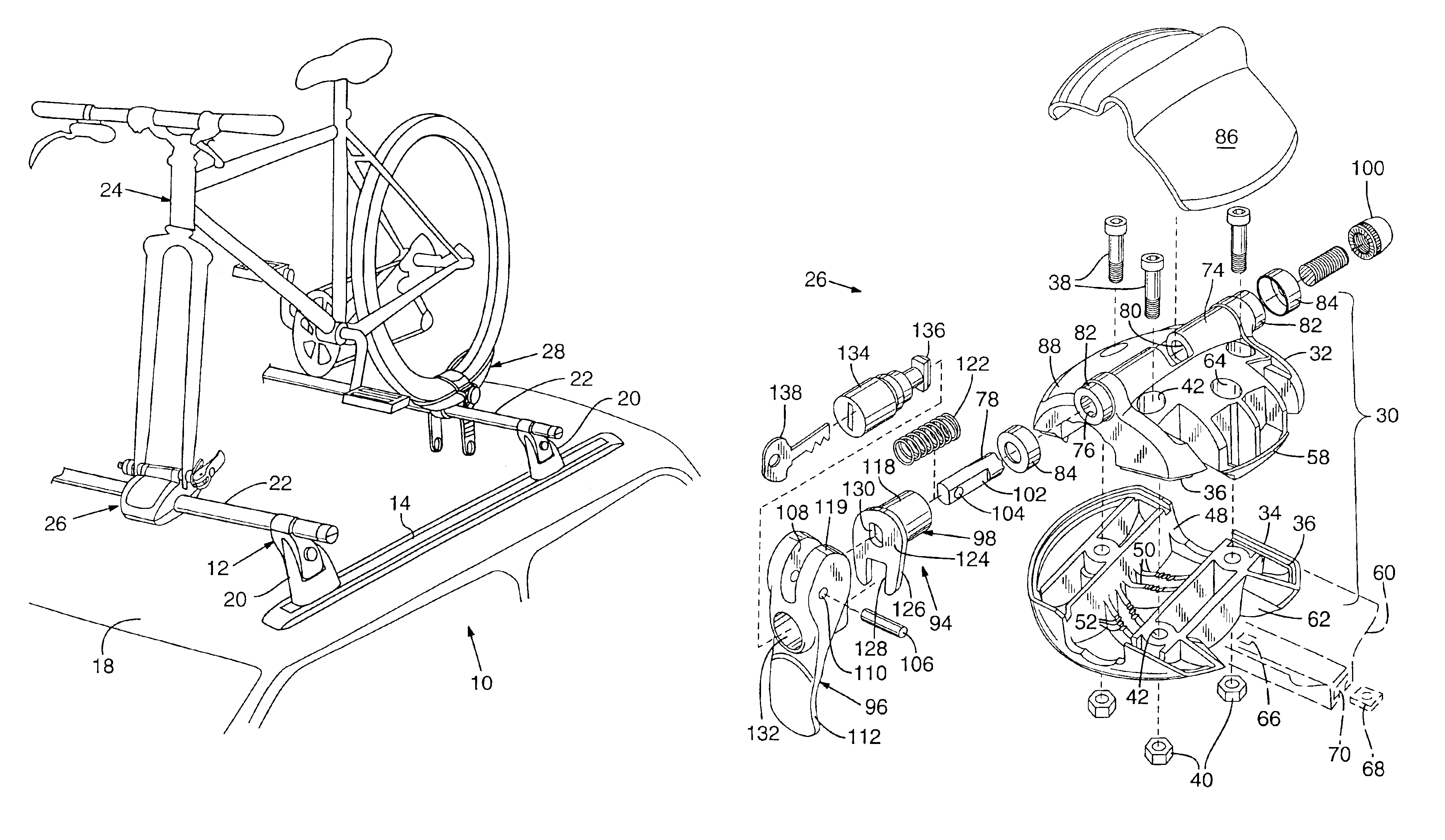
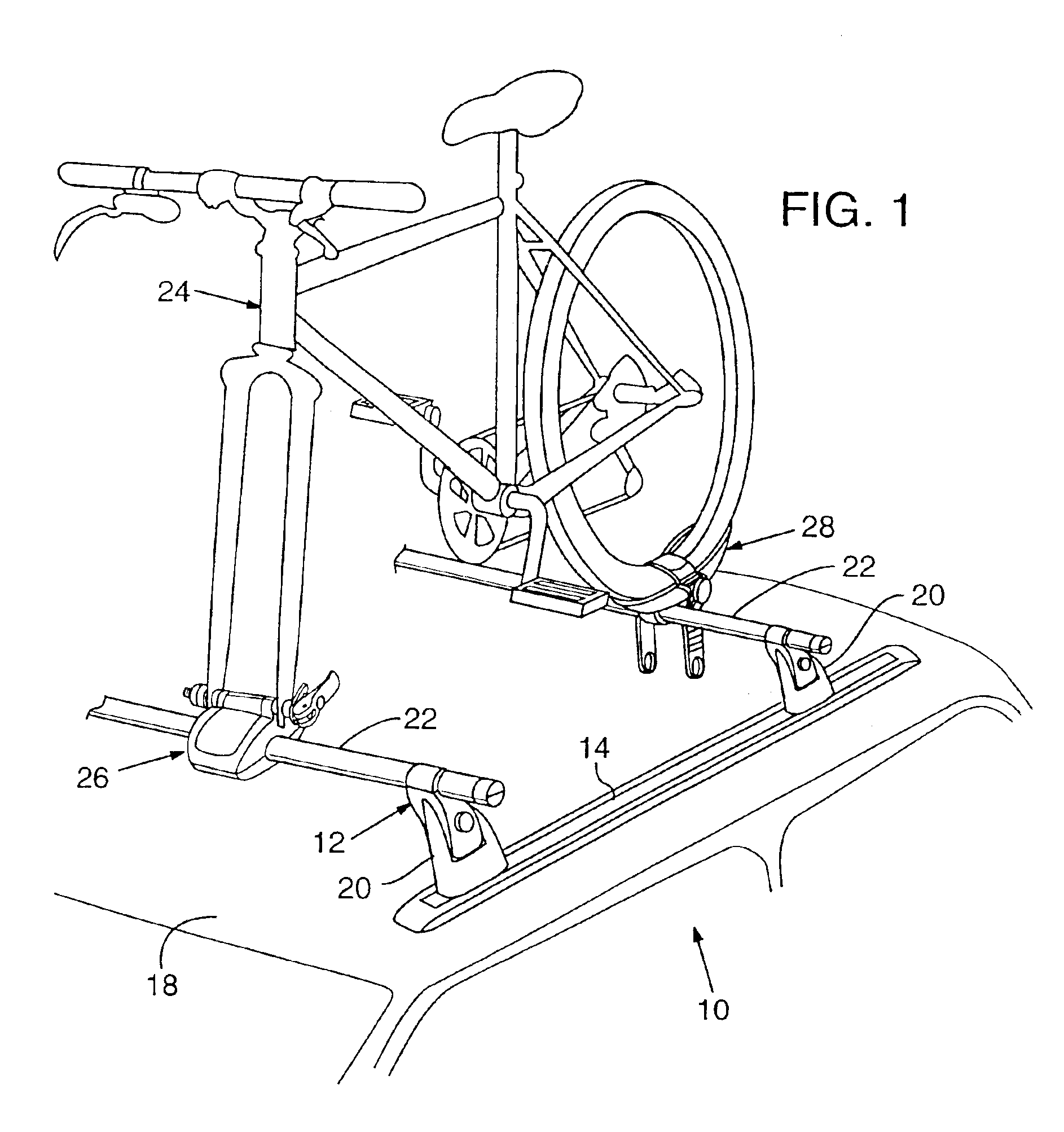
[0021]A bicycle mounting system according to the present invention is shown generally at 10 in FIG. 1. System 10 includes a roof-mounted rack 12 that attaches to factory installed tracks 14 on a roof 16 of a vehicle 18. Rack 12 includes towers 20 that interconnect the tracks to crossbars 22. A bicycle 24 is secured to the crossbars by a fork block 26 and a wheel mount 28.

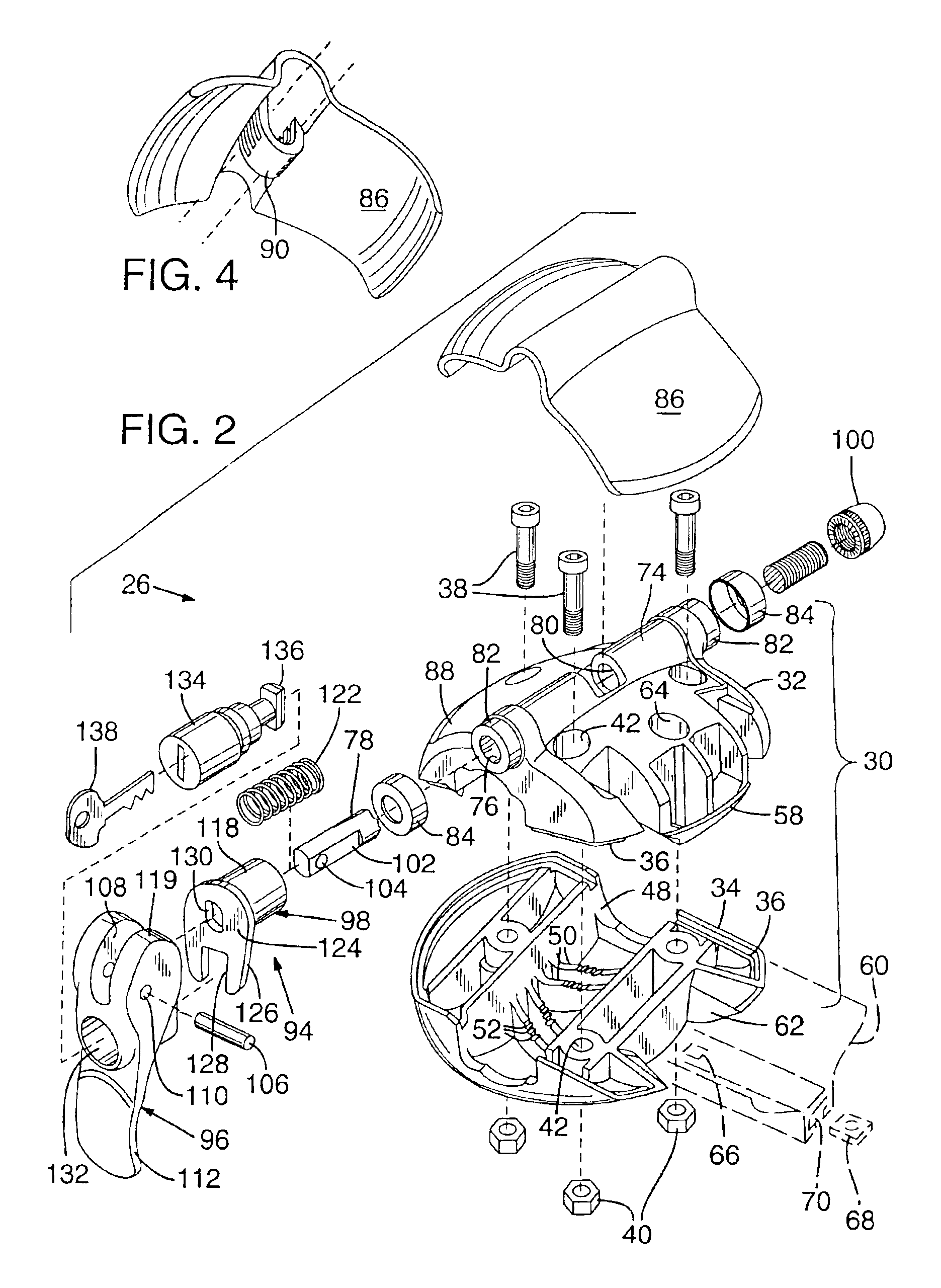
[0022]The construction of fork block 26 is shown in FIGS. 2-7. As shown in FIG. 2, fork block 26 includes a molded plastic body 30 with an upper section 32 and a lower section 34. The facing perimeters of each section are formed with stepped edges 36 that interlock with each other. The two sections are secured together by three bolts 38 that engage three corresponding nuts 40. The bolts pass through holes 42 molded in each section. A socket 44 is formed at the bottom of each hole on the lower section to receive a nut. See FIG. 3. The inside end of the socket is hexagonally shaped in cross-section to prevent the nut ...


PUM


Abstract

A rack for carrying a bicycle on a vehicle. The rack includes forward and rear crossbars extending across a top surface of the vehicle and a pair of tower bodies associated with each crossbar to secure the crossbars to the vehicle. A wheel mount is attached to a first one of the crossbars. The wheel mount is adapted to support a wheel of the bicycle with a lowest point on the wheel positioned over a range of positions relative to the crossbar including with the lowest point positioned off the wheel mount.

Description

CROSS REFERENCE TO RELATED APPLICATION[0001]This application is a continuation of U.S. patent application Ser. No. 10 / 196,330 filed Jul. 15, 2002 now U.S. Pat. No. 6,601,712 which application is a divisional application of U.S. patent application Ser. No. 09 / 910,649 filed Jul. 20, 2001 now U.S. Pat. No. 6,460,708 titled “Bicycle Carrier” which application is a divisional application of U.S. patent application Ser. No. 09 / 447,908 filed Nov. 23, 1999 now U.S. Pat. No. 6,283,310 titled “Bicycle Carrier” and are hereby incorporated by reference.FIELD OF THE INVENTION[0002]The present invention relates to bicycle carriers and more particularly to a fork block and wheel tray used to secure a bicycle on a roof rack.BACKGROUND OF THE INVENTION[0003]With the growing popularity of bicycling as a recreational activity, vehicles are often equipped with racks to transport bicycles. Such racks come in many different styles and configurations. One common configuration is a roof rack in which one o...

Claims


Application Information

Patent Timeline
IPC IPC(8): B60R9/048B60R9/00B60R9/10
CPCB60R9/048B60R9/10Y10T403/589Y10S224/924Y10T70/7322Y10T70/5872F16B2200/73
Inventor DEAN, GREGORY A.ALLEN, SCOTT R.
Owner WATERMARK PADDLESPORTS
Why Eureka
Try Eureka