Cabinet connector

Inactive Publication Date: 2005-09-06
ROUWHORST KEVIN
View PDF19 Cites 47 Cited by
  • Summary
  • Abstract
  • Description
  • Claims
  • Application Information

AI Technical Summary

Problems solved by technology

This generally takes two or three people to do and is somewhat difficult.
Releasable connectors are sometimes used to connect adjacent panels of cabinets, but the releasable connectors frequently are t

Method used


Image

  • Cabinet connector
  • Cabinet connector
  • Cabinet connector

Examples


Embodiment Construction

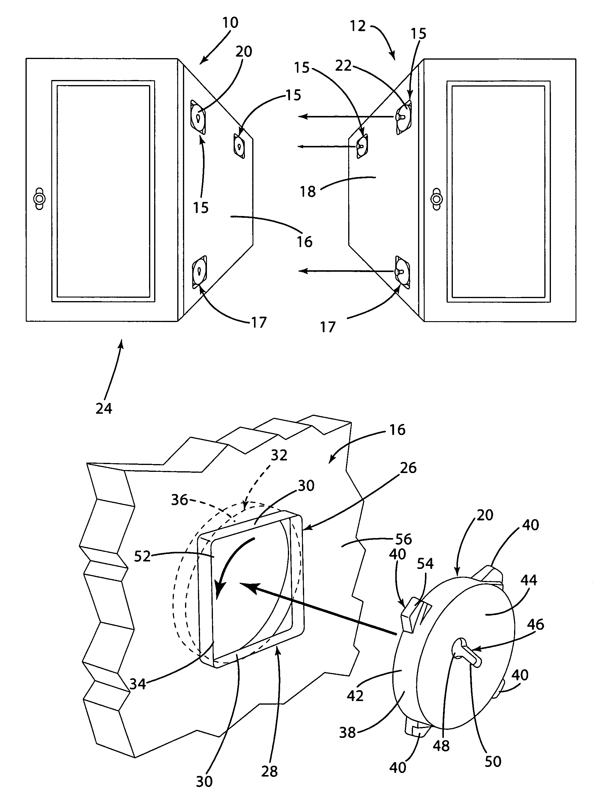
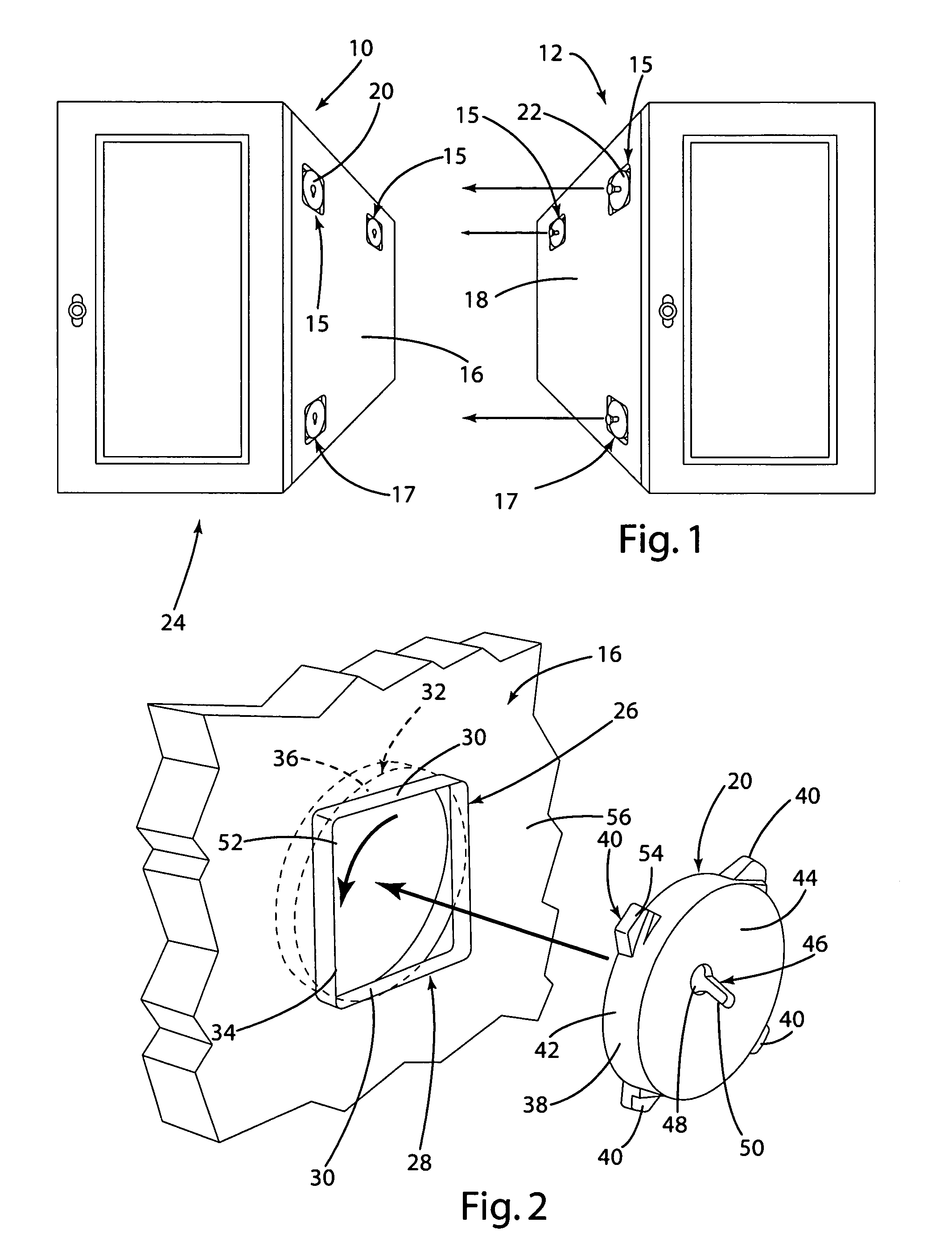
[0026]Referring to the drawings, a pair of cabinets 10 and 12 are shown in FIG. 1 in position to be joined together by means of a releasable connector mechanism 14 constructed in accordance with the present invention. Cabinets 10 and 12 typically are suspended cabinets that are attached to a wall or ceiling at an elevated position and connected together by abutting vertical sidewalls 16 and 18. In a typical installation, a first cabinet, for example cabinet 10, is mounted in position on a wall and fastened in a suspended position. The next cabinet, for example cabinet 12, is then mounted to the wall adjacent cabinet 10, with sidewalls 16 and 18 in abutment. It is difficult to mount cabinet 12 in exactly the right position with respect to cabinet 10 if the cabinets are not connected together. And it is difficult to connect the cabinets in exactly the right position. It is particularly difficult to connect the cabinets together with a connector that is sufficiently strong that the sec...


PUM


Abstract

A connector for interconnecting vertical panels of adjacent cabinets comprises male and female connector elements releasably mounted in opposed openings in the sidewalls of adjoining cabinet modules. Each connector element comprises a body that is shaped to fit into a compatible opening in a sidewall of a cabinet. The body desirably has locking tabs extending radially outwardly therefrom. The locking tabs fit into the opening in the sidewall and then are rotated into locking slots in the sides of the openings. A projection with an enlarged head on the male connector element fits in a keyhole slot in the female connector element to lock the two connector elements together.

Description

BACKGROUND OF THE INVENTION[0001]The present invention comprises a cabinet connector for releasably connecting together individual modules of a suspended cabinet system that is suspended from a ceiling or wall.[0002]Suspended cabinet systems are typically manufactured in modules and connected together side by side and mounted to a wall or ceiling. Usually, one module is mounted to the building structure and then the next module is held in place adjacent the first module while it is attached to the first module and attached to the wall or ceiling. This generally takes two or three people to do and is somewhat difficult. Releasable connectors are sometimes used to connect adjacent panels of cabinets, but the releasable connectors frequently are time consuming to install and involve more work than simply bolting the two panels together.[0003]An object of the present invention is to provide an easy to mount and easy to install connector for interconnecting adjacent vertical panels of ca...

Claims


Application Information

Patent Timeline
IPC IPC(8): F16B12/00A47B87/00A47B95/00F16B21/09
CPCA47B87/008A47B95/00F16B21/09
Inventor ROUWHORST, KEVIN
Owner ROUWHORST KEVIN
Why Eureka
Try Eureka