Method and apparatus for efficient use of communication channels for remote telemetry
- Summary
- Abstract
- Description
- Claims
- Application Information
AI Technical Summary
Benefits of technology
Problems solved by technology
Method used
Image

Examples
Embodiment Construction
[0021]The following detailed description illustrates the invention by way of example and not by way of limitation. The description clearly enables one skilled in the art to make and use the invention, describes several embodiments, adaptations, variations, alternatives, and uses of the invention, including what is presently believed to be the best mode of carrying out the invention.
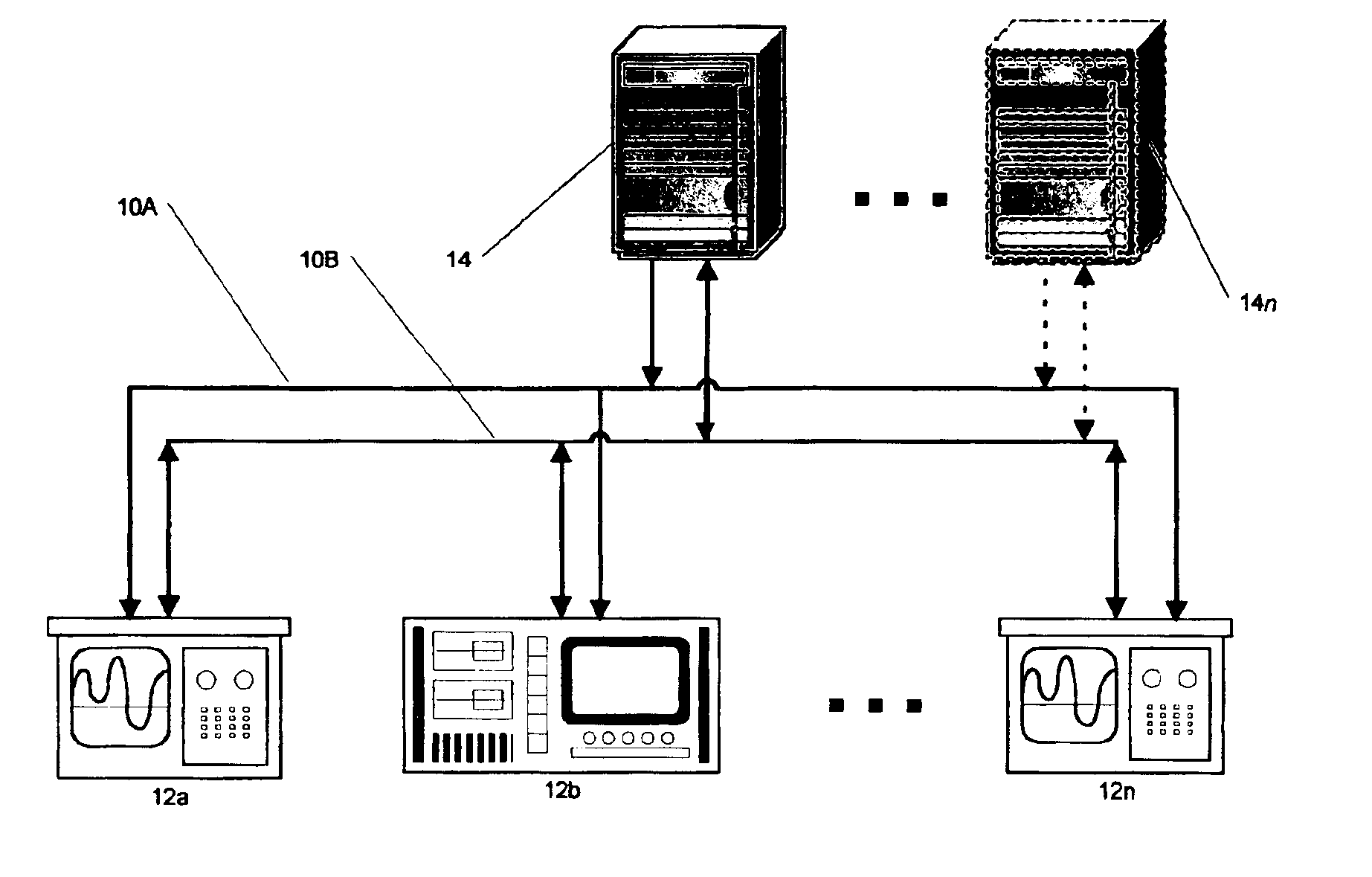
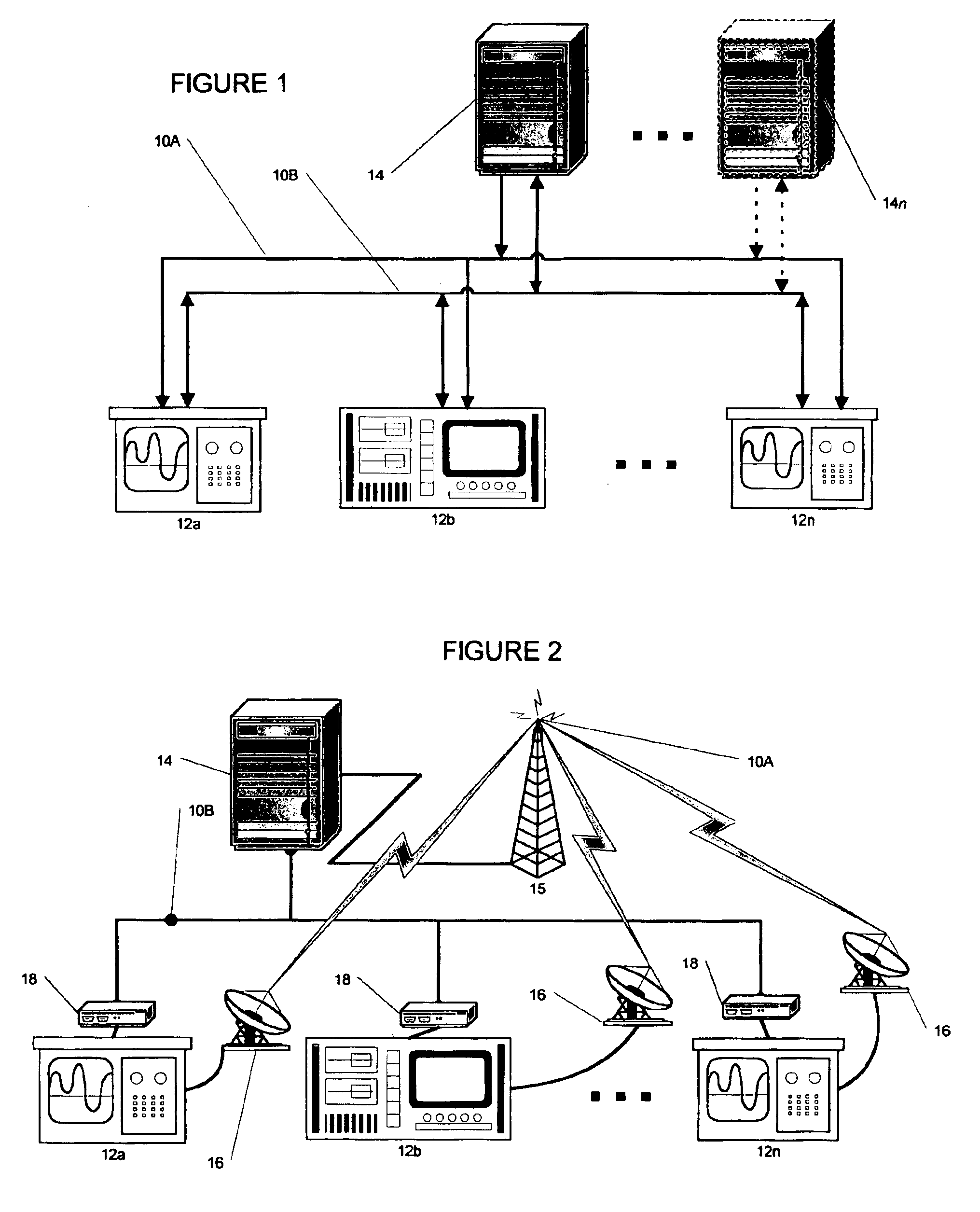
[0022]Turning to the drawings, and to FIGS. 1 and 2 in particular, the broad concept of the present invention is shown generally by the communications network 10 interconnecting a number of remote telemetry units 12a-12n, comprising one or more sets, and one or more central controllers 14-14n. The following general description is set forth in the context of a single central controller 14, and will be expanded to cover multiple central controllers 14-14n below.
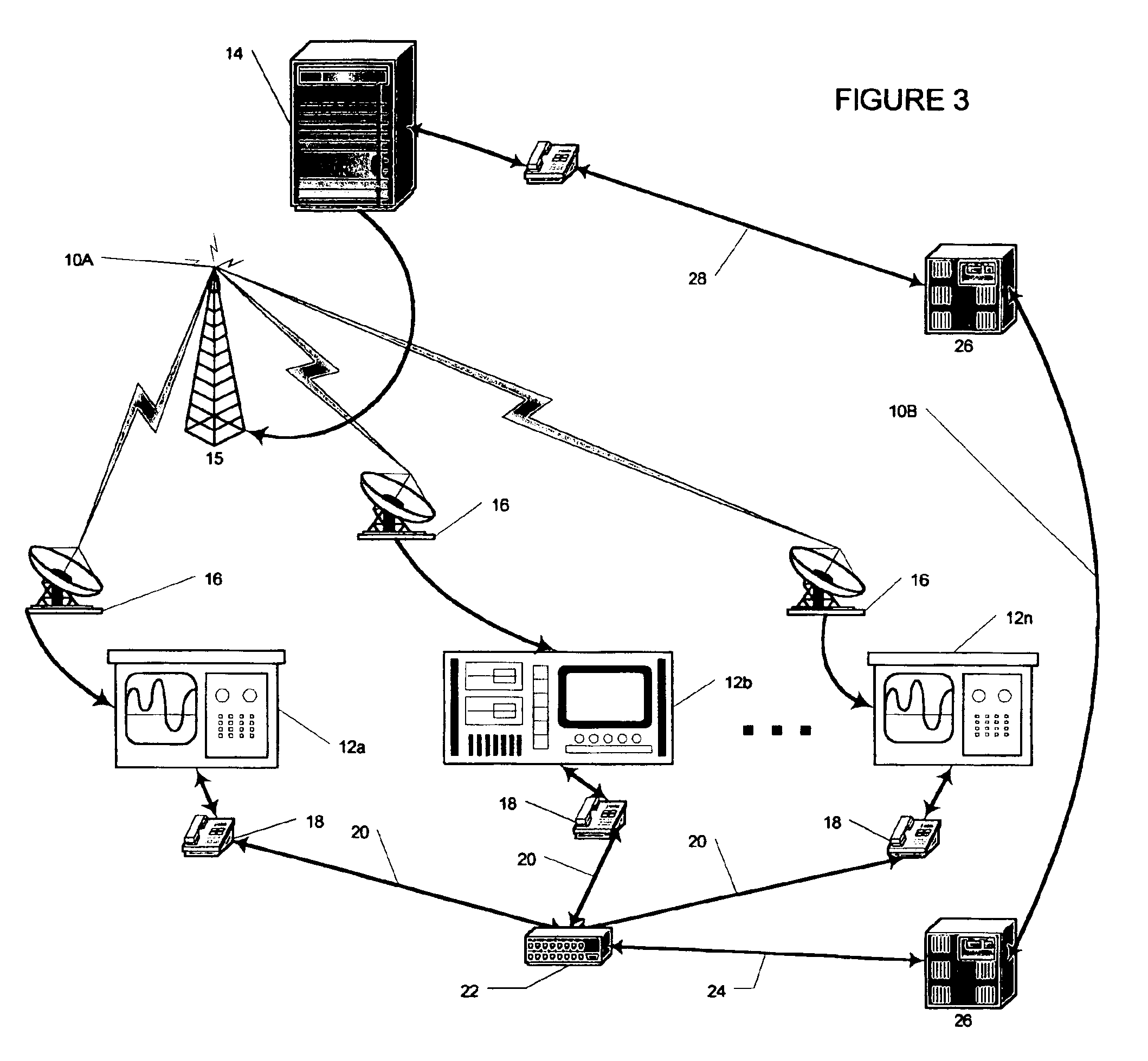
[0023]The communications network 10 comprises two separate and distinct communication pathways 10A and 10B. The first communication pathway 10A, is ...
PUM
 Abstract
Description
Claims
Application Information