
Water Purification Using Energy from a Steam-Hydrocarbon Reforming Process

a technology of water purification and hydrocarbon reforming, which is applied in the direction of energy input, separation process, contaminated groundwater/leachate treatment, etc., can solve the problems of high capital cost, large amount of waste heat, and large amount of high pressure export steam, and achieves greater heat utilization of waste heat and cost-effective

Inactive Publication Date: 2014-09-25
AIR PROD & CHEM INC
View PDF2 Cites 6 Cited by
  • Summary
  • Abstract
  • Description
  • Claims
  • Application Information

AI Technical Summary

Benefits of technology

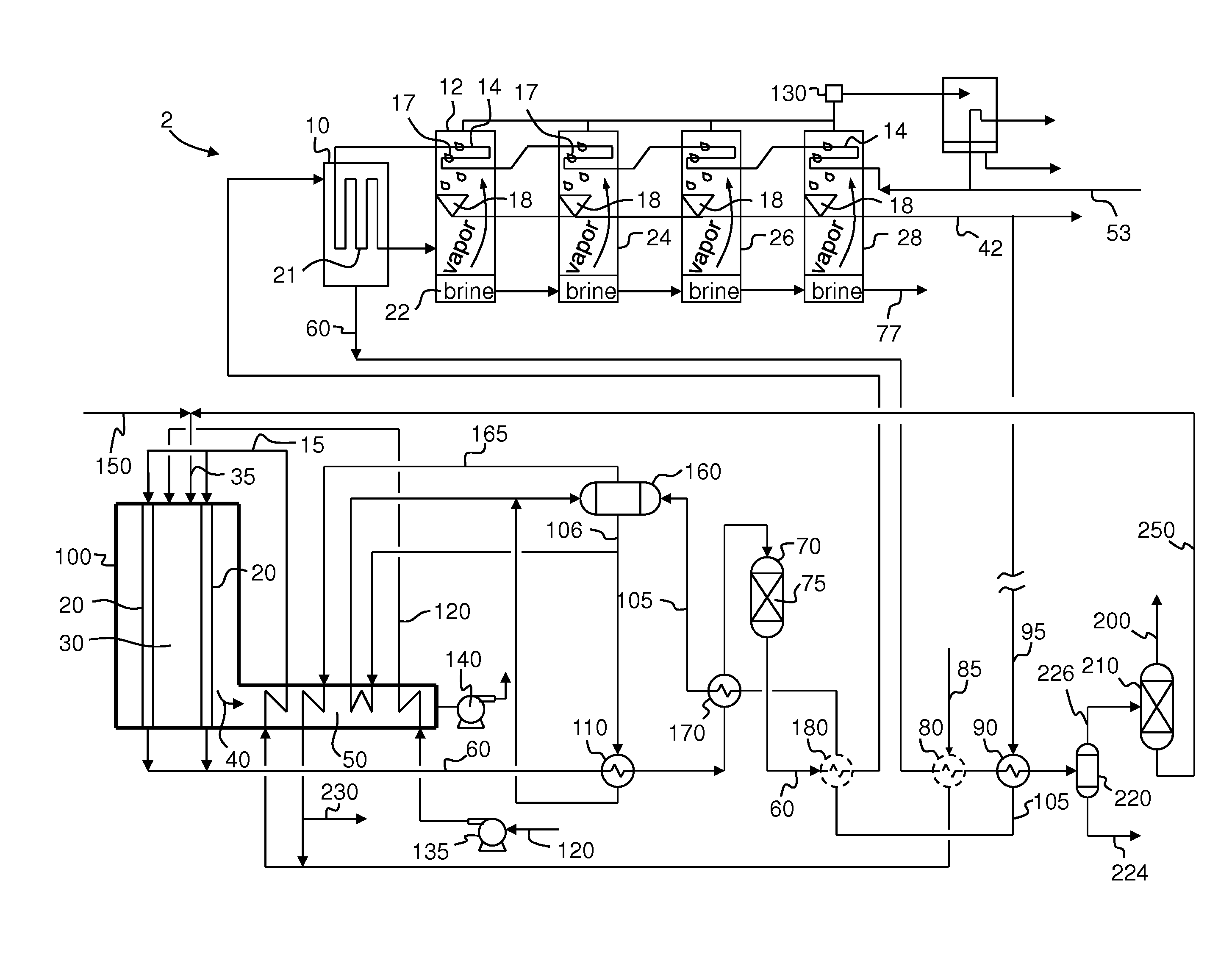
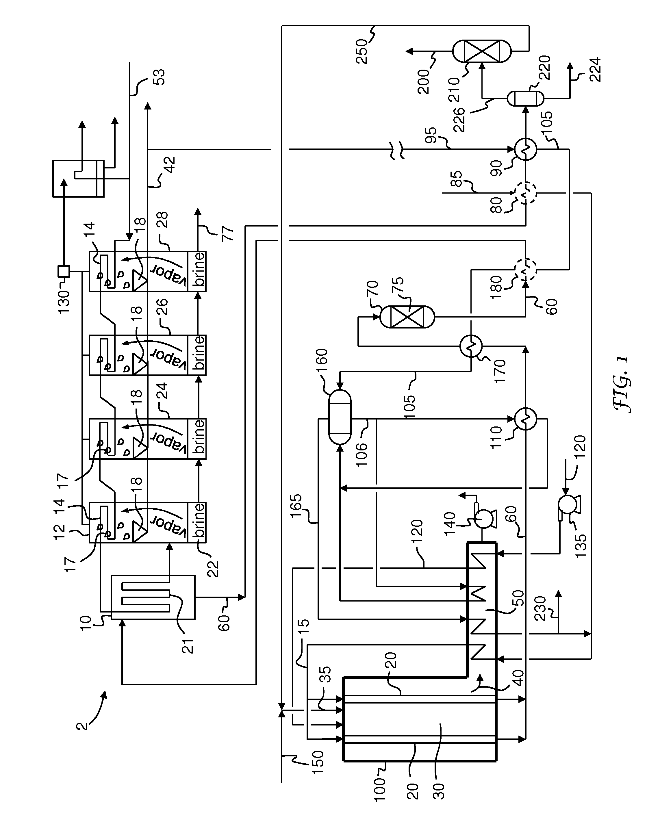
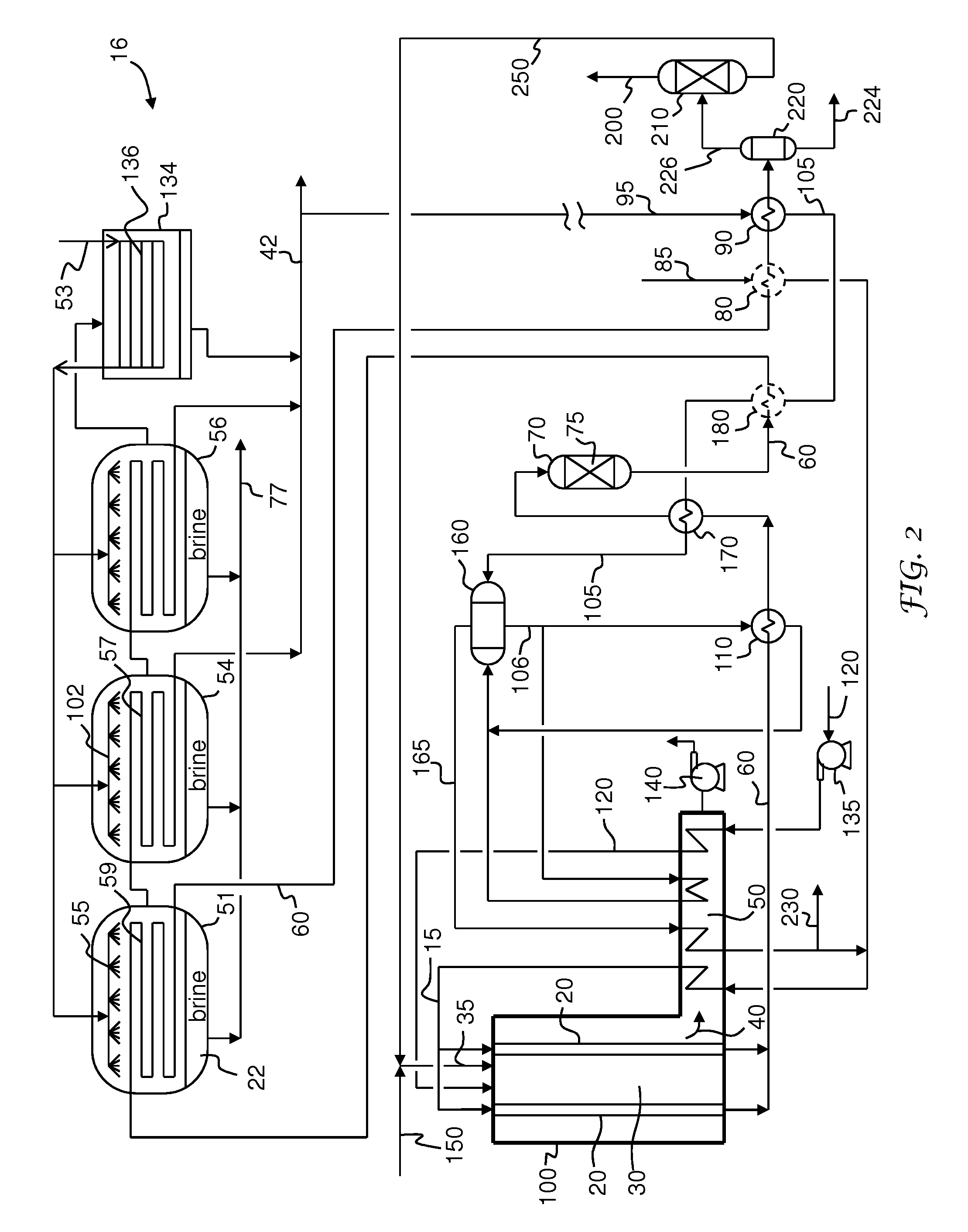
[0009]Embodiments of the present invention satisfy the need in the art by providing systems and processes for producing a H2-containing product gas and purified water from an integrated catalytic steam-hydrocarbon reforming and thermal water purification process. Embodiments of the present invention better utilize waste heat from catalytic steam-hydrocarbon reforming by using heat from the reformate in each effect or stage of the thermal water purification process. Embodiments of the present invention can reduce or eliminate costs associated with dissipating excess waste heat and can also provide flexibility to balance heat load and other operating conditions across the thermal water purification process.

Problems solved by technology

Catalytic steam-hydrocarbon reforming processes release a large amount of waste heat under various circumstances.
Another circumstance is when the process does not produce a large amount of high pressure export steam due to the lack of demand for export steam.
Low or zero export steam production reduces the heat sink for the process, resulting in a large amount of waste heat.
However, recovering more heat means using more and / or larger heat exchangers, resulting in higher capital cost.

Method used


Image

  • Water Purification Using Energy from a Steam-Hydrocarbon Reforming Process
  • Water Purification Using Energy from a Steam-Hydrocarbon Reforming Process
  • Water Purification Using Energy from a Steam-Hydrocarbon Reforming Process

Examples


example

[0230]The following is an example showing the heat utilization of the embodiment of FIG. 2 as compared to the embodiment of FIG. 7. Certain simulation parameters and simulated data have been excluded from the following discussion for clarity.

[0231]Example 1 is based on the embodiment shown in FIG. 2. The reformate is withdrawn from the SMR unit upstream of a heat exchanger (e.g., heat exchanger 90) for preheating SMR make-up water with reformate, and optionally, another heat exchanger (e.g., optional heat exchanger 80) for preheating the hydrocarbon feed with reformate. The reformate is fed to a first evaporator of a series of evaporators of the MED unit at 159 C and returns to the SMR unit at 144 C after providing the heat for water evaporation in the first evaporator of the MED unit. The amount of the reformate heat utilized in the MED unit for producing purified water is 47.9 GJ / hr. The return reformate is used in the SMR unit to heat the make-up water. The reformate is then cool...


PUM

PropertyMeasurementUnit
temperatureaaaaaaaaaa
wt %aaaaaaaaaa
pressureaaaaaaaaaa

Abstract

A process and system for producing a H2-containing product gas and purified water from an integrated catalytic steam-hydrocarbon reforming and thermal water purification process. Raw water, such as salt water, is heated by indirect heat transfer with reformate from the catalytic steam reforming process for purifying raw water in one of a multiple effect distillation process and a multi-stage flash process.

Description

CROSS-REFERENCE TO RELATED APPLICATIONS[0001]This patent application is a divisional of U.S. patent application Ser. No. 14 / 061,157, filed Oct. 23, 2013, which is a continuation-in-part of U.S. patent application Ser. No. 13 / 858,363, filed Apr. 8, 2013, now U.S. Pat. No. 8,709,287, which claims the benefit of Provisional Application Ser. No. 61 / 648,662, filed on May 18, 2012, the contents of each of which are hereby incorporated by reference as if fully set forth.BACKGROUND[0002]Thermal water purification processes, such as thermal desalination of salt water using multi-stage flash (MSF) or multiple effect distillation (MED), use heat from a low-pressure, high-quality steam energy source to effect the water purification process. Low pressure steam is generated using common boiler technology (cf. U.S. Pat. Nos. 4,338,199 and 5,441,548).[0003]It is known to use other forms of energy for desalination. For example, U.S. Pat. No. 5,421,962 utilizes solar energy for desalination processes...

Claims


Application Information

Patent Timeline
Patent Type & Authority Applications(United States)
IPC IPC(8): B01D3/06C02F1/16
CPCC02F1/16B01D3/065C01B3/384C02F1/06C01B2203/0233C01B2203/0283C01B2203/043C01B2203/0495C01B2203/0816C01B2203/0827C01B2203/0883C02F1/048C02F2103/007C02F2103/06C02F2103/08Y02W10/37Y02P20/129Y02A20/124B01D3/146
Inventor PENG, XIANG-DONGHOKE, JR., BRYAN CLAIR
Owner AIR PROD & CHEM INC
Learn More