
Convertible flashlight-headlamp

a headlamp and flashlight technology, applied in the field of convertible headlamps, can solve the problems of general awkward use, headlamp designs, and headlamps mounted to the side of the head as headlamps, and achieve the effect of modulating power delivery

Inactive Publication Date: 2005-10-11
ALLEN DAVID M
View PDF35 Cites 124 Cited by
  • Summary
  • Abstract
  • Description
  • Claims
  • Application Information

AI Technical Summary

Benefits of technology

This patent describes a portable lighting device with a battery that has a feature called a switching means to manage how power is delivered to the lights. This feature could have different forms like a flexible membrane or a controller with multiple settings including an off mode, brightness levels, and even a protective mode to conserve energy. A small computer brain (called a microprocessor) may also be used to handle these functions. Overall, this technology allows for greater flexibility and efficiency in managing power consumption for portable lighting devices.

Problems solved by technology

The technical problem addressed in this patent text is the inconvenience and lack of flexibility when wearing traditional portable lighting devices like flashlights and headlamps. There is a need for a single device that combines the functionality of both flashlights and headlamps, allowing users to easily transition between them without having to carry multiple components.

Method used


Image

  • Convertible flashlight-headlamp
  • Convertible flashlight-headlamp
  • Convertible flashlight-headlamp

Examples


Embodiment Construction

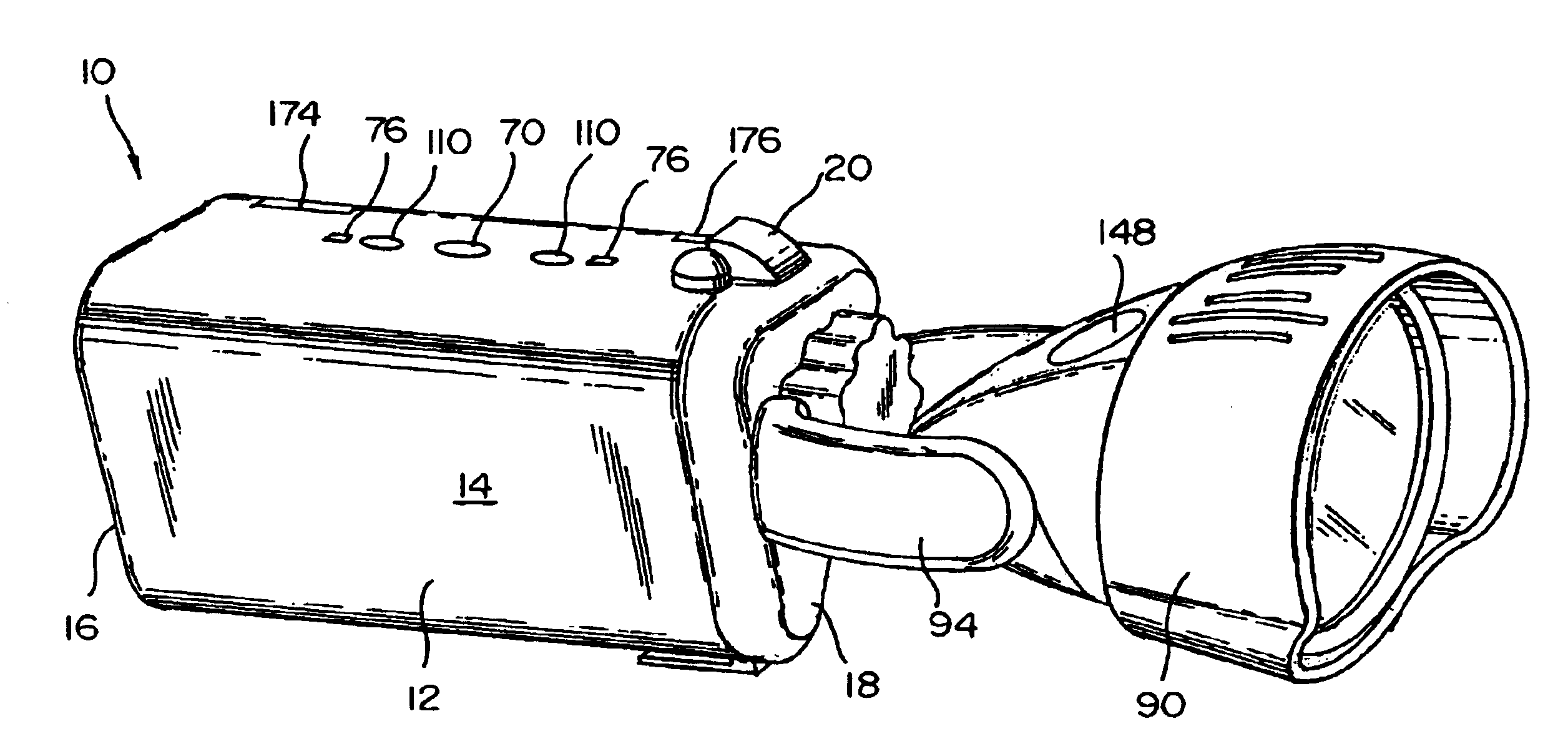
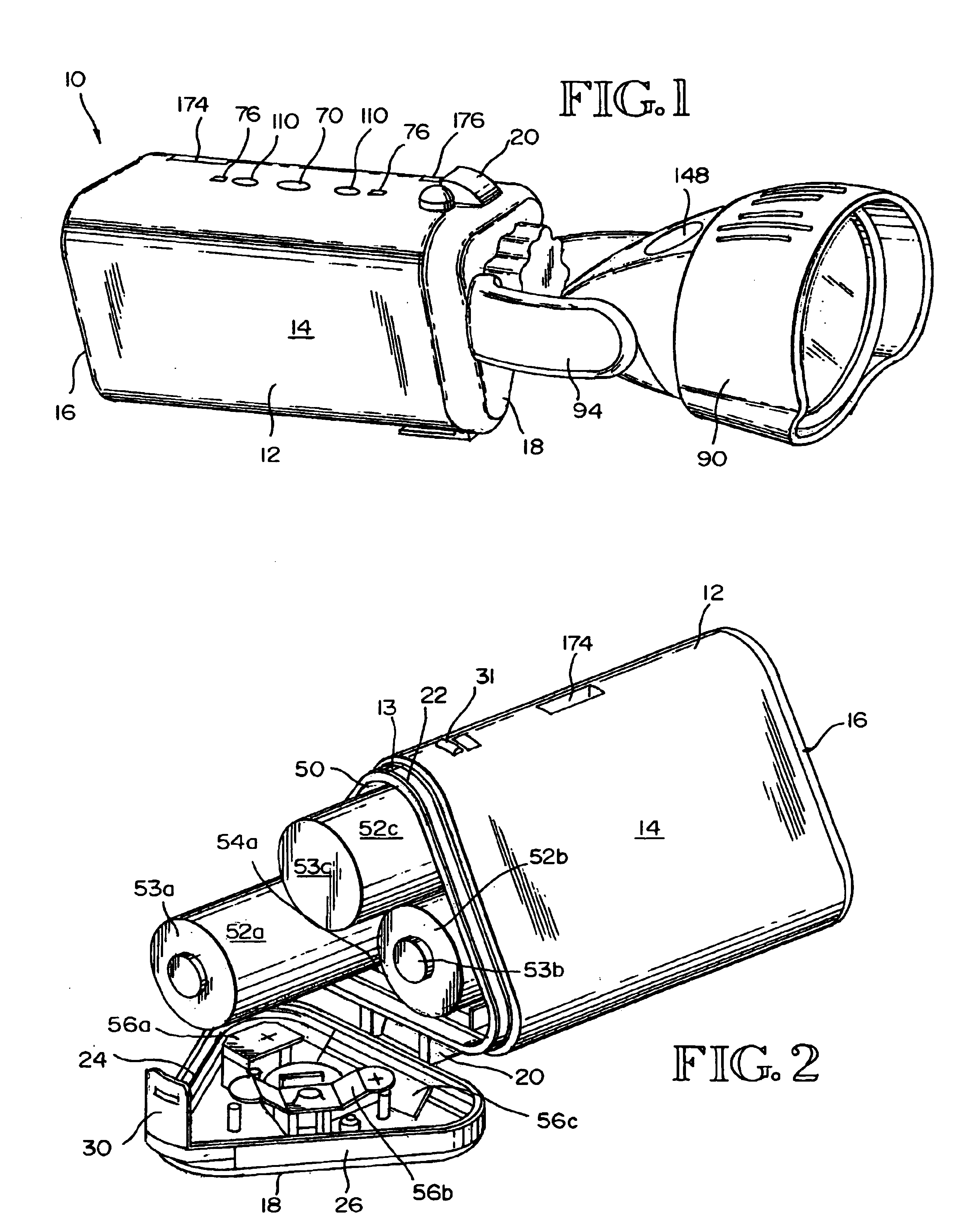
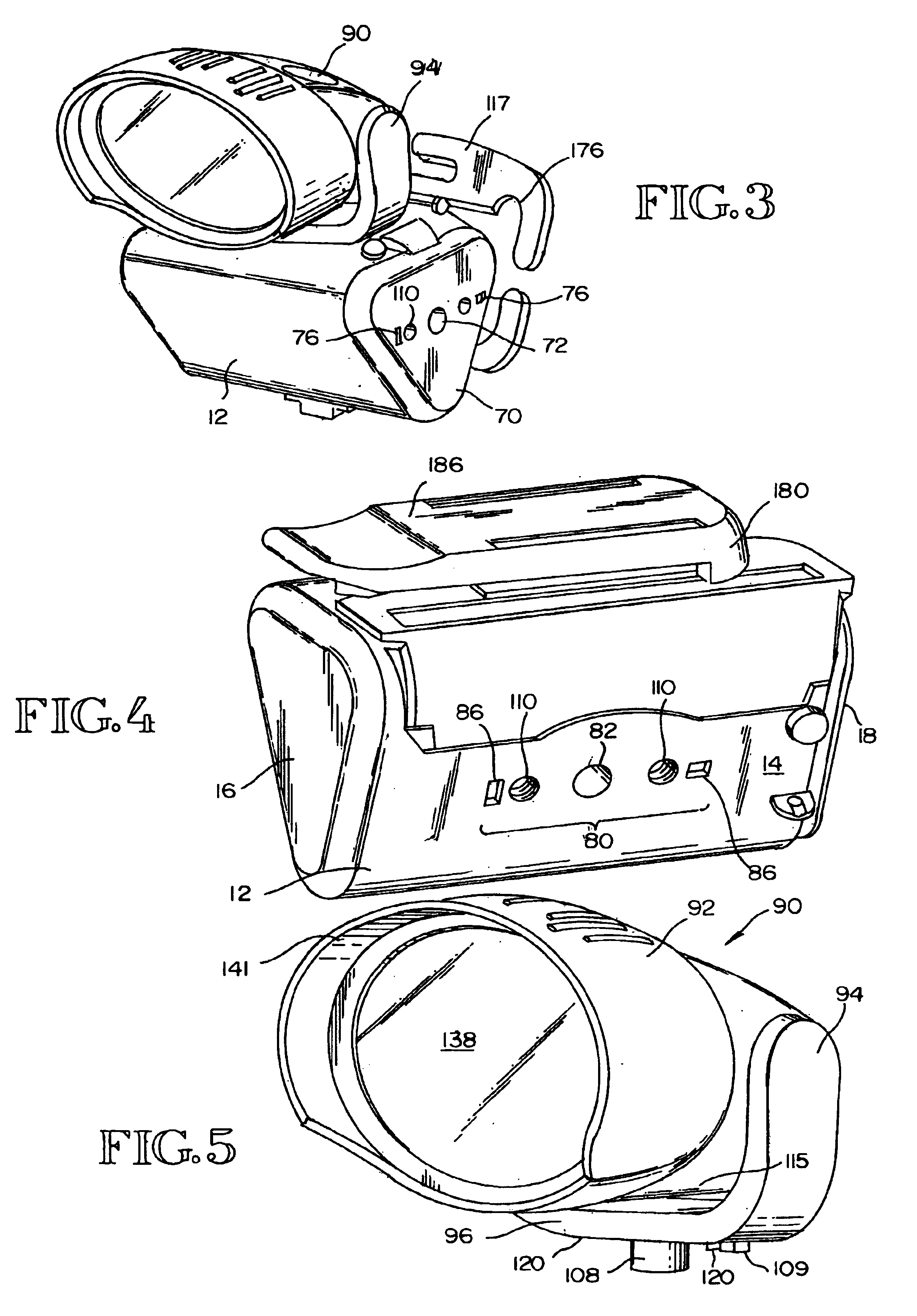
[0021]The present invention provides a convertible and portable lighting device featuring a battery housing and a detachable lamp assembly. The lighting device can be operated in flashlight and headlamp modes. The battery housing has at least two mounting ports. A first mounting port is typically located on the top portion of the battery compartment. When the lamp assembly is connected to the first mounting port, the lighting device can be operated in a flashlight mode. A second mounting port is typically located on one of the side portions of the battery housing. When the lamp assembly is connected to the second mounting port, the lighting device can be operated in a headlamp mode.

[0022]The lamp assembly features a lamp housing connected by a pair of arms to a mounting flange. The lamp housing is pivotable between the arms, so that the lamp housing can be rotated fore and aft. The lamp housing is sized and dimensioned to receive one or more lamps, such as light emitting diodes. (As...


PUM


Abstract

The instant invention provides a convertible lighting device featuring a battery housing and a detachable lamp assembly. The lighting device can be operated in flashlight and headlamp modes.

Description


Claims


Application Information

Patent Timeline
Owner ALLEN DAVID M
Learn More