Method of osmotic energy harvesting using responsive compounds and molecules

a technology of osmotic energy and responsive compounds, applied in the field of osmotic energy production and capture using responsive compounds and molecules, can solve the problems of limiting the economic feasibility of the power system, limiting improvements, and salinity fluctuations in sensitive ecosystems, so as to achieve less negative environmental impact, improve efficiency and economic effect, and deliver osmotic power more efficiently and economically

Active Publication Date: 2020-06-23
KING ABDULLAH UNIV OF SCI & TECH +1
View PDF5 Cites 2 Cited by
  • Summary
  • Abstract
  • Description
  • Claims
  • Application Information

AI Technical Summary

Benefits of technology

[0010]The present invention is a novel osmotic power system that uses stimuli responsive draw solutions, economically feasible larger permeable membranes, and low grade heat sources to deliver osmotic power more efficiently and economically with less negative environmental impact, greater power output, and more flexibility of being located in more geographically diverse areas of the world than previously thought possible.
[0011]The present invention uses a group of novel thermally responsive draw solutions, which can generate osmotic pressures comparable (or even higher) than those of brines from hypersaline lakes. These new types of stimuli responsive draw fluids or combinations of draw fluids include, but are not limited to, ionic liquids and other molecules having LCST (lower critical solubility temperature) or UCST (upper critical solubility temperature). These novel draw solutions, used in conjunction with the present invention, enables energy harvesting systems to be located in many different geographic locations and also eliminates the necessity of carrying out extensive intake pretreatment and discharge operations (which are energy intensive activities).
[0012]Due to the much larger molecular size of the novel draw solutions used in the present invention (larger than NaCl), less expensive non-RO type membranes (such as nanofiltration (NF) or even ultrafiltration (UF) membranes) with a much larger permeability can now be utilized in the present PRO system. Accordingly the nresent invention uses new types of larger permeable membranes than previously thought could be used in an osmotic power system, and these larger permeable membranes make the generation of power less expensive.
[0013]Further, the present invention can use low grade thermal energy like industrial waste heat, solar heat or geothermal heat for the external stimuli of the novel draw solutions used in the present invention, which means the present system would be supported in many different geographic areas that possesses an abundance of such low grade thermal energy. The use of low grade thermal energy also reduces the overall energy consumption required to operate existing osmotic power systems, and reduces the need to generate high grade thermal energy or power to sustain operations such as fluid intake, discharge, pretreatment, or other energy consumptive activities that compromise the net energy output and cost of operation of the power system.
[0014]The present invention can also operate as a closed regenerative system, which would reduce the negative environmental impact experienced by existing open osmotic power systems using natural feed and draw fluid sources. The present invention can also be located in a variety of geographic areas having little or no fresh / brackish (hypersaline) water interfaces. That is, instead of relying on the natural occurrence of a salinity (or concentration) gradient between seawater and river water (or between RO brine and brackish water supplies), the present invention would be supported by the regeneration of the concentration gradient of the draw solutions through the application of an external stimuli, such as heat that can be in the form of industrial waste heat, solar heat or geothermal heat. Essentially, the energy harvesting systems described herein can use low grade thermal energy as an efficient way of using liquids that have LCST or UCST phase behavior.
[0015]The present invention discloses and claims a more efficient and economical method and system for osmotic energy production and capture through the use of responsive solutions. The present invention is an energy harvest system enabled by stimuli responsive draw solutions which improve efficiency of energy production and result in greater geographic location flexibility, and more affordable, efficient and economical production and delivery of osmotic power.

Problems solved by technology

The problems currently associated with known osmotic power systems include the following: (1) limited geographic locations where there is an abundance of saline or hypersaline solutions and fresh river water used for feed and draw solution sources; (2) limited osmotic pressures that exist near sea level (seawater's osmotic pressure is approximately 27 bar, which is not sufficient to make PRO energetically competent); (3) membrane permeability problems limit the power system's economic feasibility (existing membranes are permeable for the sizes of Na+ and Cl− in the solute, which limits improvements without sacrificing selectivity); (4) environmental harm to certain animal or plant species resulting from the discharge of the brackish water from existing types of osmotic power systems, which can cause salinity fluctuations to sensitive ecosystems; and (5) net energy reductions resulting from energy required for operation of open systems, including energy consumed during intake, discharge, and pretreatment of feed and draw solutions.
Plans for further development and construction of additional osmotic power plants has been suspended by Statkraft based on the problems experienced with the pilot plant operations.
Enhancing the draw solution's osmotic pressure can be achieved by choosing brines from RO plant or hypersaline lakes (e.g., Dead Sea, Great Salt Lakes), but this solution does not resolve all the problems mentioned above, although such modifications can enhance the power density achieved by prior art systems to a small degree.

Method used


Image

  • Method of osmotic energy harvesting using responsive compounds and molecules
  • Method of osmotic energy harvesting using responsive compounds and molecules
  • Method of osmotic energy harvesting using responsive compounds and molecules

Examples


Embodiment Construction

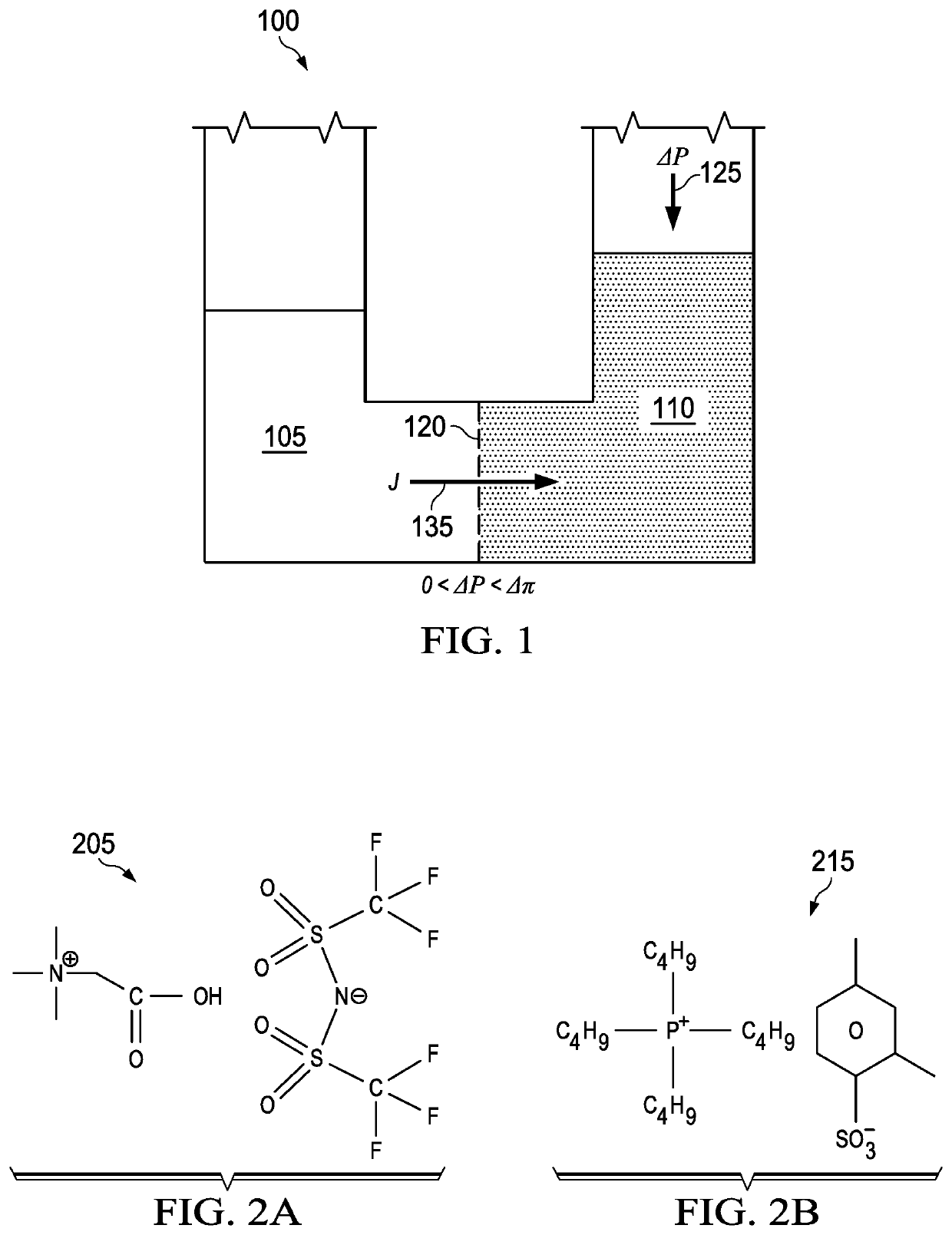
[0030]To describe with principles of the present invention, a diagram of a system for harvesting of salinity gradient energy by PRO is schematically shown in FIG. 1. In FIG. 1, a schematic diagram of a general osmotic liquid pressure chamber 100 is shown with a semi-permeable membrane 120 placed between two solutions, which include a feed solution (pure water, lower concentration) 105 and draw solution (e.g. saline water, higher concentration) 110. The semi-permeable membrane 120 can reject solute, but allows the passage of water feed solution 105 into the draw solution 110.

[0031]The concentrated draw solution 110 (draw solution / saline water) has a higher osmotic pressure AP 125, and the other diluted feed solution 105 has a lower osmotic pressure (feed solution / pure water). The symbol J 135 denotes the osmotic water flux direction that occurs when a lower hydraulic pressure is imposed on the draw solution 110 compared to the osmotic pressure difference across the membrane 120. This...


PUM


Abstract

The present invention discloses and claims a more efficient and economical method and system for osmotic energy production and capture using responsive compounds and molecules. The present invention is an energy harvest system enabled by stimuli responsive draw solutions that are competent in terms of energy production, geographic location flexibility, and the affordable, efficient and economical production and delivery of osmotic power. Specifically, the present invention is a novel osmotic power system that uses stimuli responsive draw solutions, economically feasible larger permeable membranes, and low grade heat sources to deliver osmotic power more efficiently and economically with less negative environmental impact, greater power output, and located in more geographically diverse areas of the world than previously thought possible for supporting such a power source.

Description

CROSS-REFERENCE TO RELATED APPLICATIONS[0001]This application is the National Stage of International Application No. PCT / IB2017 / 050292, filed Jan. 19, 2017, which claims the benefit of and priority to Singapore Provisional Patent Application Serial No. 10201600442R filed Jan. 20, 2016, which is incorporated herein by reference in its entirety.RELATED APPLICATION DATA[0002]This application claims the benefit of Singapore Provisional Patent Application Serial No. 10201600442R filed Jan. 20, 2016.TECHNICAL FIELD[0003]The present invention relates to a method and system for osmotic energy production and capture using responsive compounds and molecules.BACKGROUND OF THE INVENTION[0004]According to the International Energy Agency, the current global energy supply is overwhelmingly originated from fossil fuel combustion, and only a small portion of our world-wide energy needs are supplied by renewable resources such as solar, wind, wave, geothermal and hydroelectric power sources. Internat...

Claims


Application Information

Patent Timeline
Patent Type & Authority Patents(United States)
IPC IPC(8): F03G7/00B01D61/00B01D61/44F24T50/00F03B17/06B01D61/58F24S90/00
CPCF03B17/06F03G7/005B01D61/44F24S90/00B01D61/58B01D61/005F24T50/00B01D61/002Y02E10/10F24T10/00Y02E10/20Y02E10/40
Inventor HU, XIAOCAI, YUFENGLAI, ZHIPINGZHONG, YUJIANG
Owner KING ABDULLAH UNIV OF SCI & TECH
Why Eureka
Try Eureka