Self-locking linear adjustment mechanism

a linear adjustment and self-locking technology, applied in the direction of screws, rod connections, screws, etc., can solve the problem of costly construction

Inactive Publication Date: 2005-10-11
TYLOSKY GORDON
View PDF59 Cites 33 Cited by
  • Summary
  • Abstract
  • Description
  • Claims
  • Application Information

AI Technical Summary

Benefits of technology

The technical effect of this patent is to create better parts or ways of arranging them that make up a cheap and reliable self-locking linear adjustment mechanism. This mechanism works well and meets all of its goals.

Problems solved by technology

The technical problem addressed by this patent is the lack of a self-locking linear adjustment mechanism in various devices described earlier. This type of mechanism has been used in other fields but was not previously known to be applied to an antenna or a vehicle's engine. The solution proposed involves a new method for creating such a mechanism based upon previous art from several sources like U.S. Patents Nos. 7,05,9123,65,63,450,82, and74, and76,95, among others.

Method used


Image

  • Self-locking linear adjustment mechanism
  • Self-locking linear adjustment mechanism
  • Self-locking linear adjustment mechanism

Examples


Embodiment Construction

[0080]The present invention is a self-locking linear adjustment mechanism. The invention disclosed herein is, of course, susceptible of embodiment in many different forms. Shown in the drawings and described herein below in detail are preferred embodiments of the invention. It is to be understood, however, that the present disclosure is an exemplification of the principles of the invention and does not limit the invention to the illustrated embodiments.

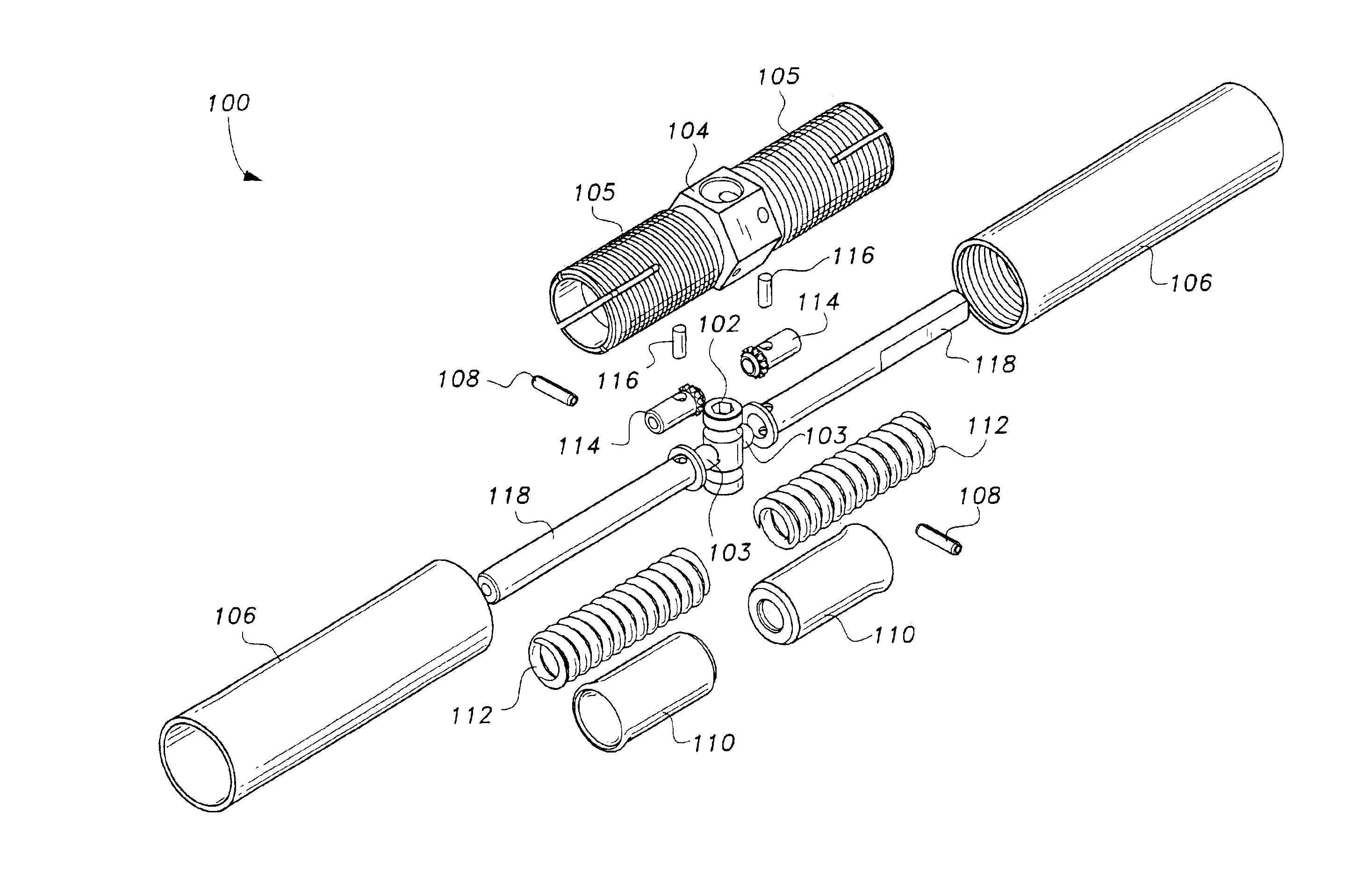
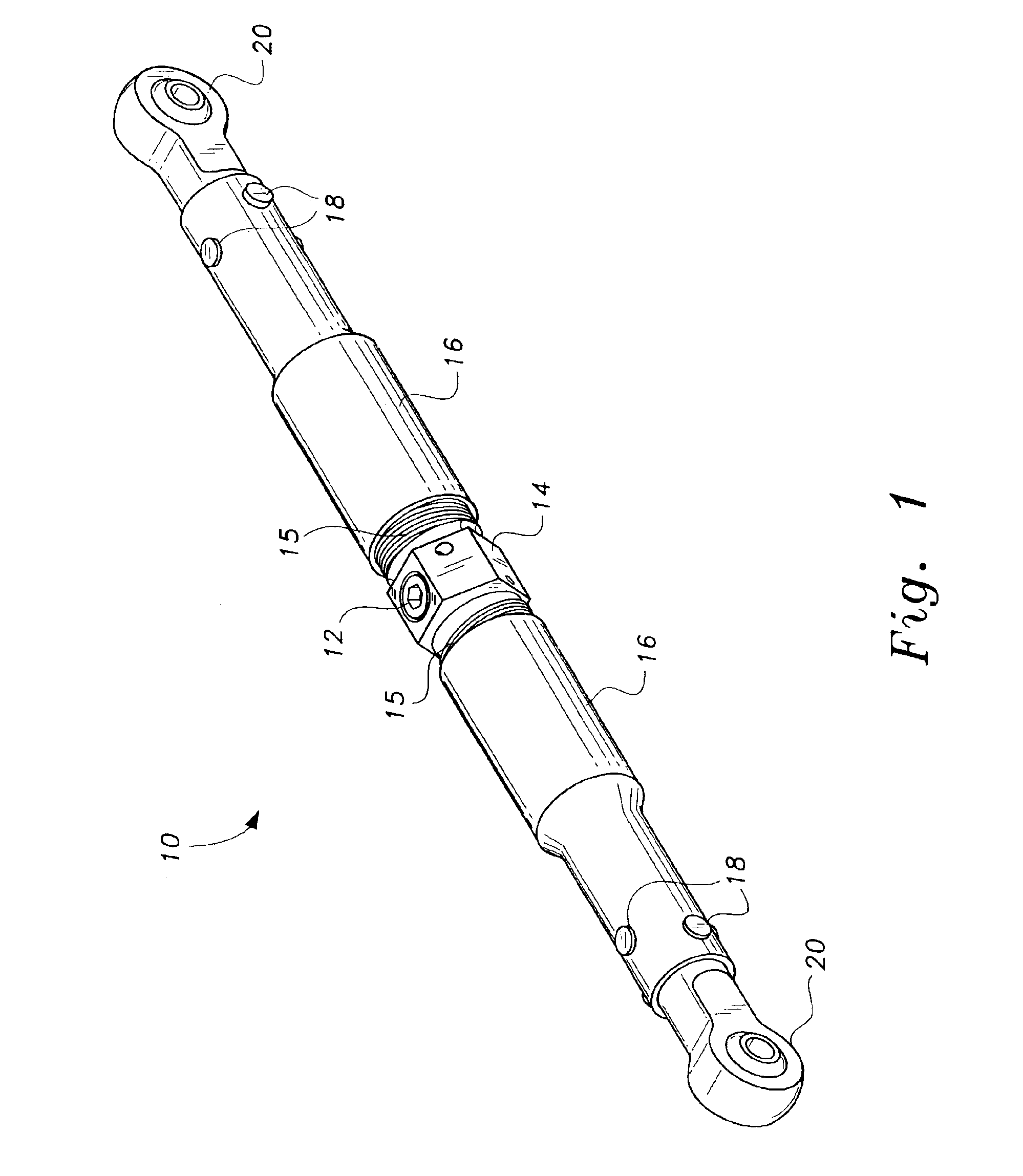
[0081]Referring to the drawings, FIG. 1 shows an example of a self-locking linear adjustment mechanism according to the present invention in the form of a complete rod assembly 10. The self-locking linear adjustment mechanism in the form of a complete rod assembly 10 enables users to provide a control rod as a single complete assembly. The self-locking linear adjustment mechanism 10 in the form of a complete rod assembly includes a locking tumbler 12, an adjustment vernier 14 with two oppositely extending tubular members 15, and two e...


PUM


Abstract

A self-locking linear adjustment mechanism may be configured in the form of a rod assembly or a cartridge assembly. The self-locking linear adjustment mechanism in the form of a cartridge assembly includes a self-locking linear adjustment mechanism including a locking tumbler, an adjustment vernier, two end adapters, two roll pins, two precision balls, two locking skirts, two springs, two locking splines, two index pins, and two guide shafts, wherein the self-locking linear adjustment mechanism has a dual function self-locking feature.

Description


Claims


Application Information

Patent Timeline
Owner TYLOSKY GORDON
Why Eureka
Try Eureka