Bifurcation graft deployment catheter

a technology for deploying catheters and vascular prostheses, which is applied in the field of endoluminal vascular prosthesis deployment catheters, can solve the problems of high mortality, abdominal wall surgery, and sac rupture, and achieve the effect of reducing the risk of surgery

a technology for deploying catheters and vascular prostheses, which is applied in the field of endoluminal vascular prosthesis deployment catheters, can solve the problems of high mortality, abdominal wall surgery, and sac rupture, and achieve the effect of reducing the risk of surgery

US6953475B2Inactive Publication Date: 2005-10-11ENDOLOGIX LLC

Image

  • Bifurcation graft deployment catheter
  • Bifurcation graft deployment catheter
  • Bifurcation graft deployment catheter

Examples


Embodiment Construction

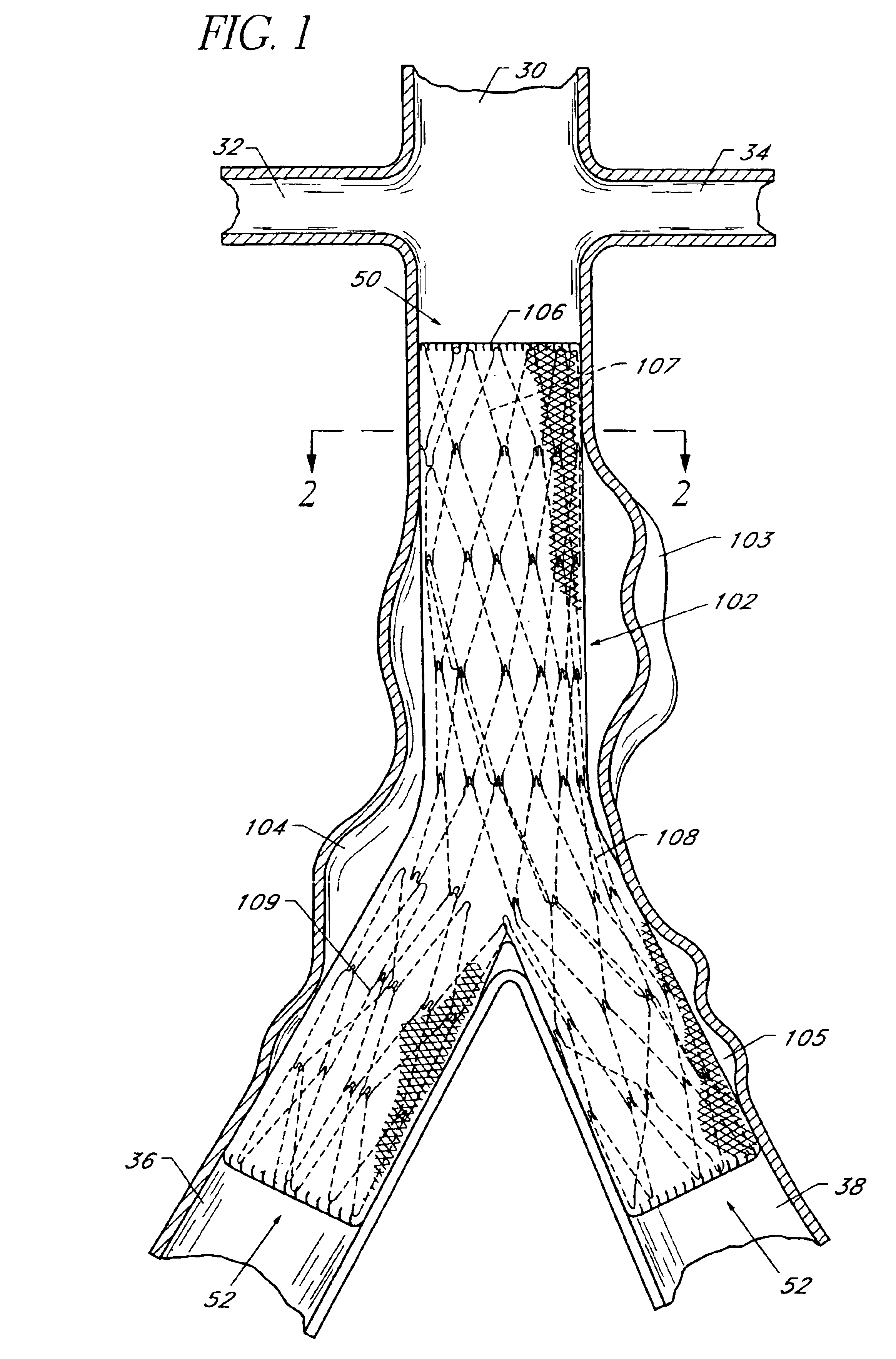
[0039]Referring to FIG. 1, there is disclosed a schematic representation of the abdominal part of the aorta and its principal branches. In particular, the abdominal aorta 30 is characterized by a right renal artery 32 and left renal artery 34. The large terminal branches of the aorta are the right and left common iliac arteries 36 and 38. Additional vessels (e.g., second lumbar, testicular, inferior mesenteric, middle sacral) have been omitted for simplification.

[0040]An expanded bifurcated endoluminal vascular prosthesis 102, in accordance with one aspect of the present invention, is illustrated spanning aneurysms 103, 104 and 105. Although certain prosthesis configurations are disclosed herein, these are only examples of prostheses which are deployable using the deployment catheter of the present invention. The deployment catheter may be used to deploy essentially any self expandable bifurcated or straight segment prosthesis, as will be apparent to those of skill in the art in vie...


PUM


Abstract

Disclosed is a deployment catheter for deploying a tubular endoluminal vascular prosthesis, useful in treating, for example, an abdominal aortic aneurysm. The deployment catheter includes a proximal tubular section and a distal tubular section which are axially movable in opposite directions to deploy a prosthesis. A central core extends throughout the proximal tubular section and into the distal tubular section. A reinforcing structure is carried by the central core, spanning the junction between the proximal tubular section and distal tubular section, to improve flexibility characteristics of the catheter. In one embodiment, the proximal tubular section and / or distal tubular section are rotationally linked to the central core.

Description

[0001]This a continuation of Ser. No. 09 / 747,094, filed Dec. 22, 2000, now U.S. Pat. No. 6,660,030, which is a continuation-in-part of Ser. No. 09 / 525,778, filed Mar. 15, 2000, now U.S. Pat. No. 6,500,202, which is a continuation-in-part of Ser. No. 09 / 251,363, filed Feb. 17, 1999, now U.S. Pat. No. 6,197,049, which is a continuation-in-part of Ser. No. 09 / 210,280, filed Dec. 11, 1998, now U.S. Pat. No. 6,187,036, the disclosures of each of which are incorporated by their entireties herein by reference.BACKGROUND OF THE INVENTION[0002]The present invention relates to endoluminal vascular prosthesis deployment catheters, and in particular, to a deployment catheter for self-expanding straight segment or bifurcated prostheses for use in the treatment of abdominal aortic aneurysms.[0003]An abdominal aortic aneurysm is a sac caused by an abnormal dilation of the wall of the aorta, a major artery of the body, as it passes through the abdomen. The abdomen is that portion of the body which ...

Claims


Application Information

Patent Timeline
11 Oct 2005
Publication
US6953475B2
IPC
A61F2/06; A61F2/00; A61F2/90
CPC
A61F2/07; A61F2/856; A61F2/90; A61F2/954; A61F2/958; A61F2002/061; A61F2002/065; A61F2002/067
Inventors
SHAOLIAN, SAMUEL M.; MADRID, GILBERT