Impact absorber for vehicle

a technology for absorbing devices and vehicles, applied in the direction of shock absorbers, elastic dampers, bumpers, etc., can solve the problems of difficult installation or replacement, complicated structure of those devices, and driver injuries

Inactive Publication Date: 2005-10-25
LEUNG KAM HANG
View PDF25 Cites 14 Cited by
  • Summary
  • Abstract
  • Description
  • Claims
  • Application Information

AI Technical Summary

Problems solved by technology

Although part of the impact energy will be absorbed as described, much of the impact energy will remain unabsorbed and be applied continuously to the vehicle, hence injuring the driver.
Furthermore, the structures of those apparatus are complicated and not easy to install or replace.

Method used


Image

  • Impact absorber for vehicle
  • Impact absorber for vehicle
  • Impact absorber for vehicle

Examples


Embodiment Construction

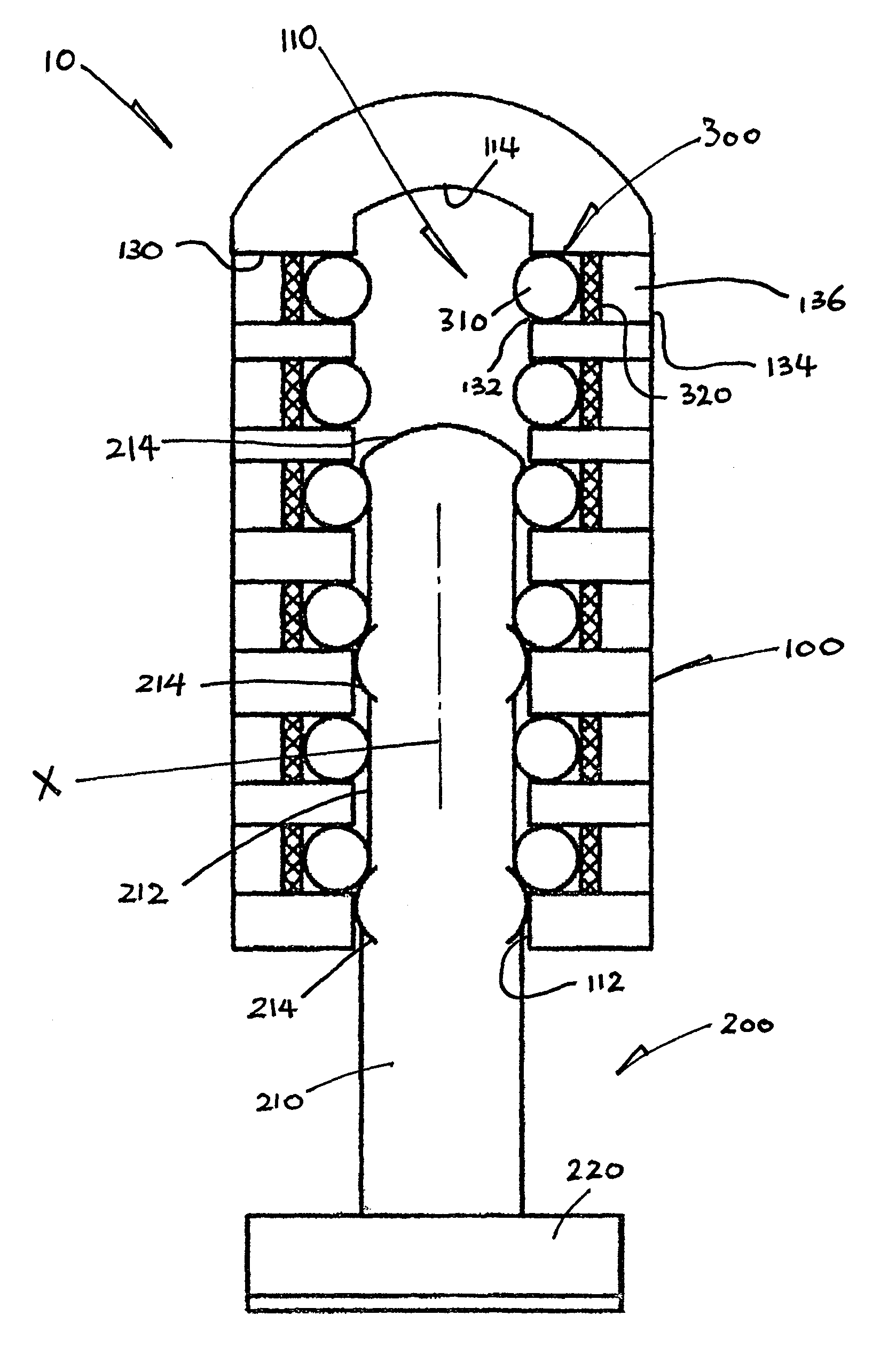
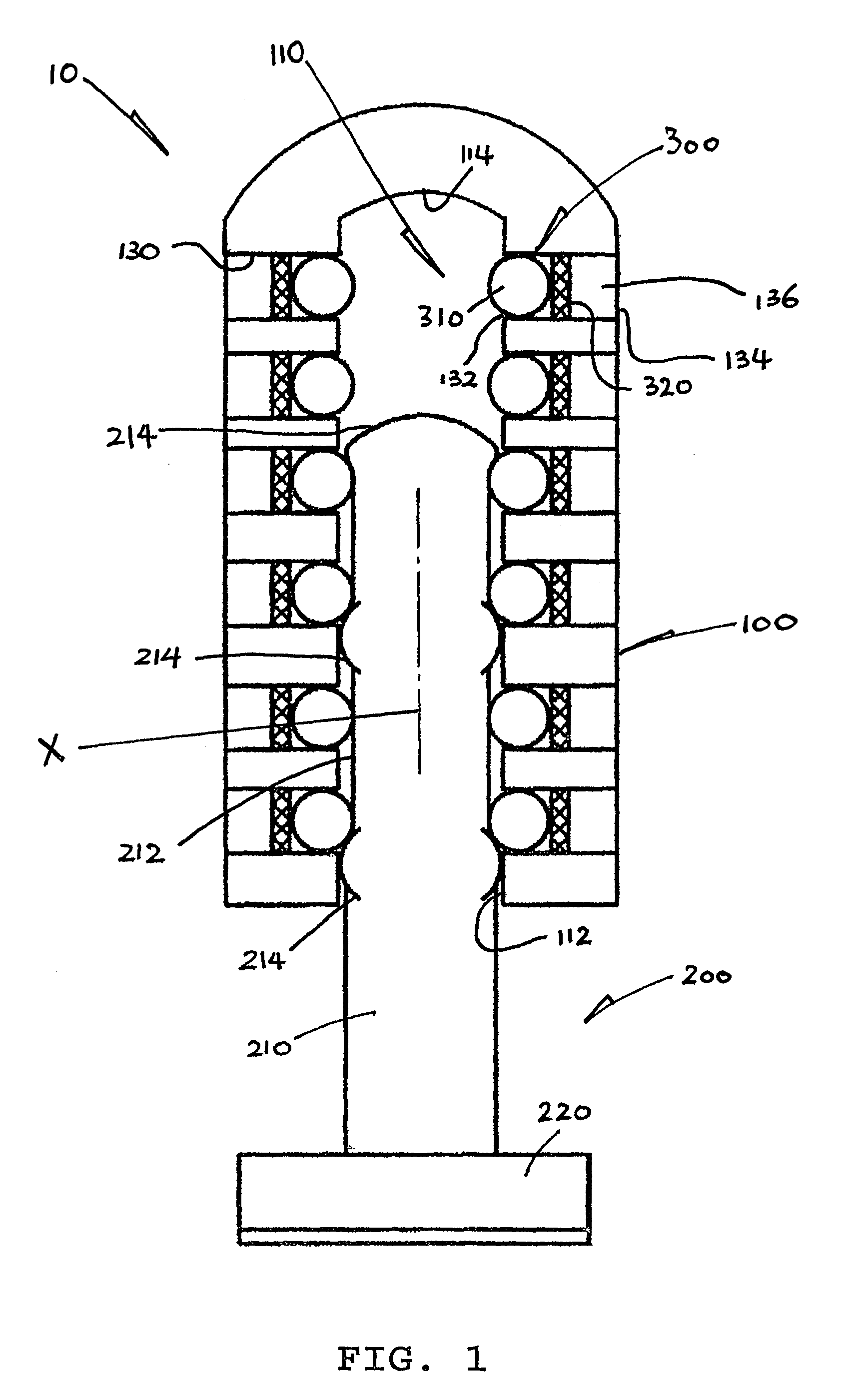
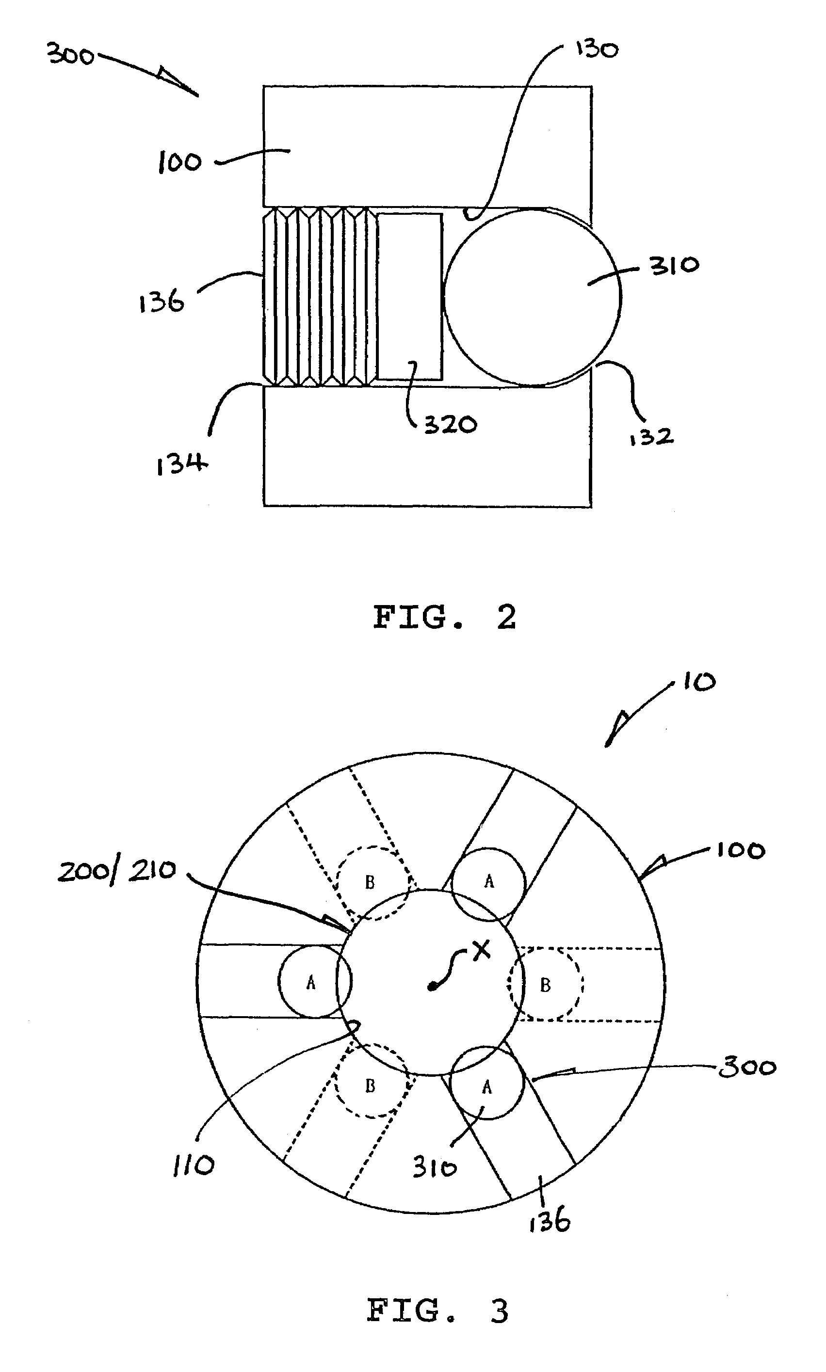
[0023]Referring to the drawings, there is shown an impact absorber 10 embodying the invention for use in a motor vehicle 20, for example mounted right behind a front bumper 22 thereof, which absorber 10 has an outer cylinder 100, an inner rod 200 and eighteen deformable units 300. The cylinder 100 has a generally cylindrical central cavity 110 that shares a common axis X with the cylinder 100 and has an open end 112 and a closed end 114.

[0024]The rod 200 has a shaft 210 having a cylindrical surface 212 and a buffer disc 220 connected co-axially at one of the shaft ends. Three annular ribs 214 are formed on the shaft 210 protruding radially therefrom, which extend around the shaft 210 at evenly spaced positions along the shaft axis. Each rib 214 has a rounded convex cross-section that protrudes slightly from the surface 212 of the shaft 210. The outer diameter of the shaft 210, i.e. including the ribs 214, is marginally smaller than the diameter of the cavity 110.

[0025]The shaft 210 ...


PUM

PropertyMeasurementUnit
angleaaaaaaaaaa
angleaaaaaaaaaa
energyaaaaaaaaaa

Abstract

An impact absorber for a vehicle includes an outer body including a cavity having an axis, and an inner body situated partially within the cavity for relative movement into the cavity when the absorber is subjected to an impact. The inner body has at least one lateral protrusion. A number of deformable units are located in the outer body at different positions along the cavity. The deformable units partially protrude into the cavity for successive engagements and deformations, one unit after another unit, along the cavity, by the protrusion of the inner body moving into the outer body, thereby absorbing the energy of an impact in different stages. Each deformable unit includes a rigid ball protruding into the cavity and a deformable plate fixed behind the ball.

Description

[0001]The present invention relates to an impact absorber for use in a motor vehicle and, particularly, but not exclusively, in a bumper thereof.BACKGROUND OF THE INVENTION[0002]Impart energy absorbing apparatus for motor vehicles are known, for example as disclosed in U.S. Pat. Nos. 3,392,599, 3,788,148, 4,006,647 and 5,984,354. Such apparatus, which are intended for use in the steering shaft of a vehicle, comprise a shaft enclosed by an outer cylindrical sleeve in a telescopic manner, and a number of balls rotatably mounted in the gap between the shaft and the sleeve. Upon impact, the sleeve and shaft collapse relative to each other, with the balls continuously rolling therebetween to absorb the impact energy.[0003]Although part of the impact energy will be absorbed as described, much of the impact energy will remain unabsorbed and be applied continuously to the vehicle, hence injuring the driver. Furthermore, the structures of those apparatus are complicated and not easy to insta...

Claims


Application Information

Patent Timeline
Patent Type & Authority Patents(United States)
IPC IPC(8): B60R19/26B60R19/38B60R19/24B60R19/34F16F7/12
CPCB60R19/26B60R19/34B60R19/38F16F7/126
Inventor LEUNG, KAM HANG
Owner LEUNG KAM HANG
Why Eureka
Try Eureka