Rolling bearing arrangement for an electromotor

Inactive Publication Date: 2005-11-22
REXROTH INDRAMAT
View PDF5 Cites 25 Cited by
  • Summary
  • Abstract
  • Description
  • Claims
  • Application Information

AI Technical Summary

Benefits of technology

[0011]It is the object of the present invention to create a rolling bearing arrang

Problems solved by technology

The flow of current causes damage to the rolling bearings.
Current-damaged bearings have typical transverse corrugations on the raceway that lead to vibrations and noise before the bearing finally fails.
Although conductive constituents—such as graphite—is added to this grease, the experiment showed no important change in the insulating properties of the lubricant film, and so an

Method used


Image

  • Rolling bearing arrangement for an electromotor
  • Rolling bearing arrangement for an electromotor

Examples


Embodiment Construction

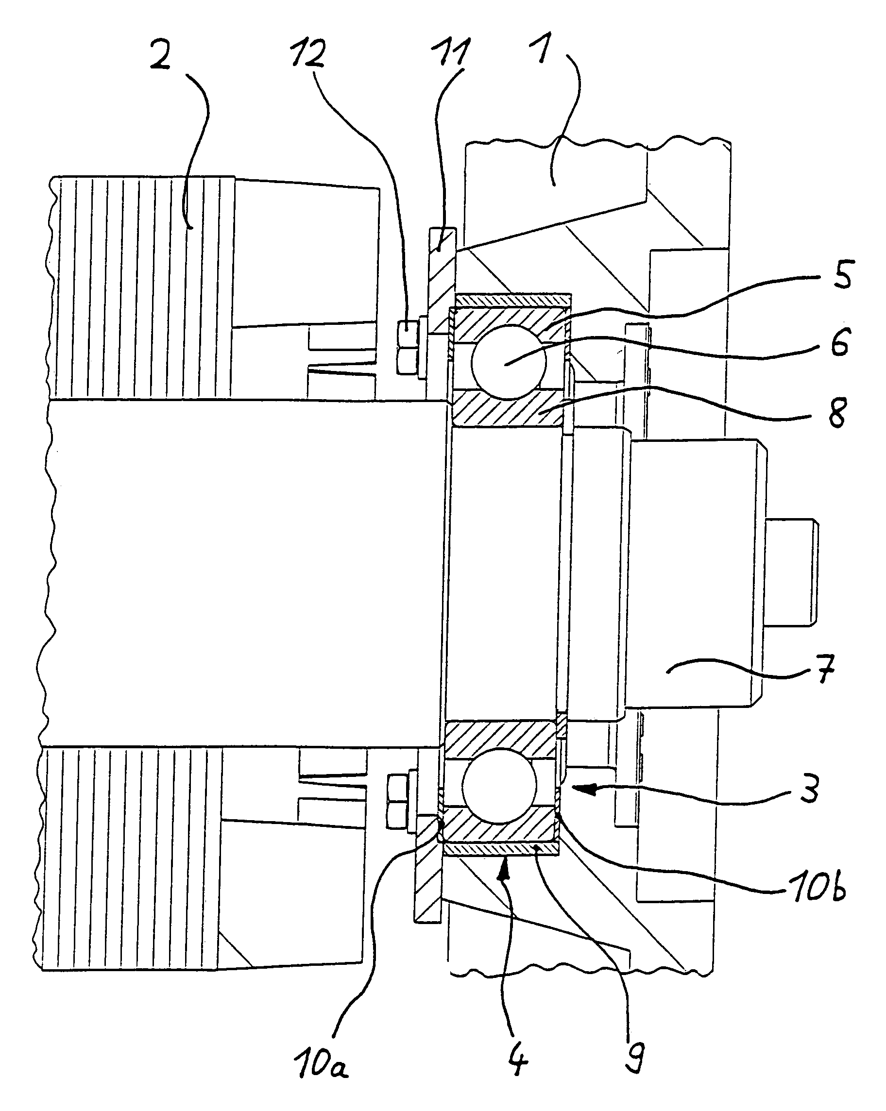
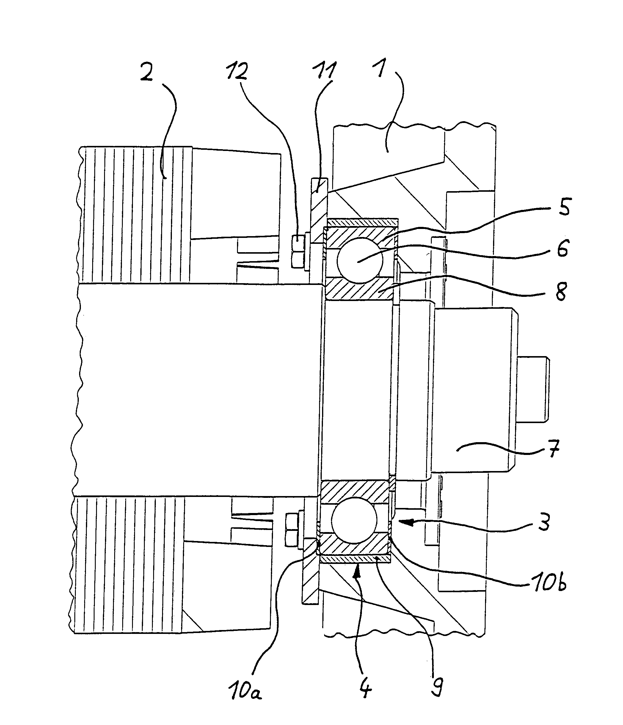
[0018]The electromotor, designed as an asynchronous motor, essentially comprises a stator 1 with reference to which a rotor 2 is rotatably arranged. A rolling bearing 3 in the form of a ball bearing is provided for rotationally bearing the rotor 2 in the stator. The rolling bearing 3 is held in a fixed position relative to the stator 1 in a bearing seat 4 constructed therein. In this case, the bearing seat 4 cooperates with an outer ring or race 5 of the rolling bearing 3. The outer ring 5 is connected, for the purpose of rotary bearing, via a rolling body arrangement 6, here spherical rolling bodies, to an inner ring or race 8 arranged on a shaft 7 of the rotor 2.

[0019]The bearing seat 4 is lined with an insulation arrangement bearing current that spreads onto the stator 1 starting from the rotor 2, via the shaft 7 thereof and via the rolling bearing 3. The insulation arrangement is of multipart construction and comprises a hollow cylindrical element 9 on which an annular disk elem...


PUM


Abstract

The invention relates to a rolling bearing arrangement for an electromotor having a rotationally symmetrical rotor arranged rotatably inside a stator, there being provided for rotationally bearing the rotor. At least one standard rolling bearing that has an outer race which is arranged in a bearing seat in a fixed position relative to the stator and which cooperates via a rolling body arrangement with an inner race arranged on a shaft of the rotor. The bearing seat is lined with an insulation arrangement in order to avoid a flow of current between stator and rotor, the insulation arrangement having a thin, sheet-type semifinished product having insulation material resistant to the radial pressure force of the bearing.

Description

PRIORITY CLAIM[0001]This is a U.S. national stage of application No. PCT / DE01 / 02807, filed on 20 Jul. 2001. Priority is claimed on that application and on the following application: Country: Germany, Application No.: 100 37 423.9, Filed: 21 Jul. 2000.BACKGROUND OF THE INVENTION[0002]1. Field of the Invention[0003]The invention relates to a rolling bearing arrangement for an electromotor having a rotor rotatably arranged inside a stator, including a bearing seat which is fixed with respect to the stator, and a bearing with an outer race, an inner race, and a plurality of rolling bodies between the races, the outer race being received in the bearing seat, the inner race being arranged on the rotor shaft.[0004]2. Description of the Related Art[0005]Particularly in the case of asynchronous motors, in conjunction with applications where a constant speed prevails, a flow of current occurs between the outer stator and the rotor borne rotatably therein, the circuit being closed by the rolli...

Claims


Application Information

Patent Timeline
IPC IPC(8): F16C35/04F16C35/077F16C19/02F16C19/16H02K5/16F16C21/00H02K5/173
CPCF16C35/077H02K5/1732F16C19/06F16C2202/30F16C2380/26
Inventor SCHELBERT, JOHANNES
Owner REXROTH INDRAMAT
Why Eureka
Try Eureka