Electro-optical device and electronic apparatus

a technology of electro-optical devices and electronic devices, applied in the direction of lighting and heating devices, electric apparatus casings/cabinets/drawers, instruments, etc., can solve the problems of panel flying out, increase the number of parts and steps, and hinder the display of electro-optical devices. , the effect of preventing the adhesion base from slipping

Active Publication Date: 2005-12-29
BOE TECH GRP CO LTD
View PDF10 Cites 43 Cited by
  • Summary
  • Abstract
  • Description
  • Claims
  • Application Information

AI Technical Summary

Benefits of technology

[0007] An advantage of the invention is that it provides an electro-optical device which can prevent, for example, a liquid crystal panel from flying out of or becoming displaced from a frame, and an electronic apparatus using the electro-optical device. Another advantage of the invention is that it prevents, for example, a liquid crystal panel from flying out of or becoming displaced from a frame easily and at a low cost without increasing the number of parts and steps while preventing malfunctioning of, for example, a liquid crystal driving IC caused by light.
[0008] An electro-optical device according to a first aspect of the invention comprises an electro-optical panel, a frame, and an adhesion base. The electro-optical panel includes a substrate holding an electro-optical material, a side of the electro-optical panel for displaying an image having a display area and a non-display area. The frame holds the electro-optical panel and has at least one side wall disposed in correspondence with at least a side surface of the electro-optical panel. The adhesion base has a form extending continuously at least from the non-display area to the side wall, and is adhered to the non-display area and the side wall.
[0009] Here, “adhesion base” refers to, for example, a light-shielding member having an adhesion surface or a flexible board similarly having an adhesion surface. A separate adhesive tape may be disposed as an adhesion base in order to prevent, for example, the flying out or displacement of a liquid crystal panel.
[0010] According to the first aspect of the invention, since the adhesion base having a form which extends continuously over the non-display area of a surface of an image display side of the electro-optical panel and the side wall of the frame which holds the electro-optical panel is adhered to the side wall and the non-display area, it is possible to prevent the electro-optical panel from flying out of or becoming displaced from the frame due to, for example, shock applied to the frame. In addition, since the adhesion base is adhered to the non-display area of the electro-optical panel, it is possible to prevent the adhesion base from hindering the display of the electro-optical device.
[0011] It is preferable that the at least one side wall include a first side wall and a second side wall, the first and second side walls being disposed in correspondence with side surfaces of the electro-optical panel and opposing each other with the non-display area being disposed therebetween, and that the adhesion base have a form extending continuously at least from the non-display area to the first side wall and be adhered to the non-display area and the first side wall. Accordingly, it is possible for, for example, the adhesion base to be adhered from a portion of the first side wall of the frame to a portion of the non-display area of the electro-optical panel, so that a compact adhesion base can be used to prevent, for example, the electro-optical panel from flying out of or becoming displaced from the frame. In addition, since the first and second side walls of the frame are disposed on both sides of the non-display area of the electro-optical panel, it is possible to reliably prevent, for example, the displacement of the electro-optical panel.
[0012] An electro-optical device according to a second aspect of the invention comprises an electro-optical panel, a frame, and at least one adhesion base. The electro-optical panel includes a first substrate and a second substrate. The second substrate extends beyond the first substrate and has a protrusion on which an integrated circuit for driving an electro-optical material is mounted. The first substrate and the second substrate oppose each other with the electro-optical material being disposed therebetween. The frame holds the electro-optical panel and has at least one side wall disposed in correspondence with at least a side surface of the electro-optical panel. The at least one adhesion base has a form extending continuously at least from the protrusion to the side wall, and is adhered to the protrusion and the side wall.

Problems solved by technology

Therefore, for example, the liquid crystal panel may fly out of the frame of the liquid crystal device by, for example, external shock of an electronic apparatus.

Method used


Image

  • Electro-optical device and electronic apparatus
  • Electro-optical device and electronic apparatus
  • Electro-optical device and electronic apparatus

Examples


first embodiment

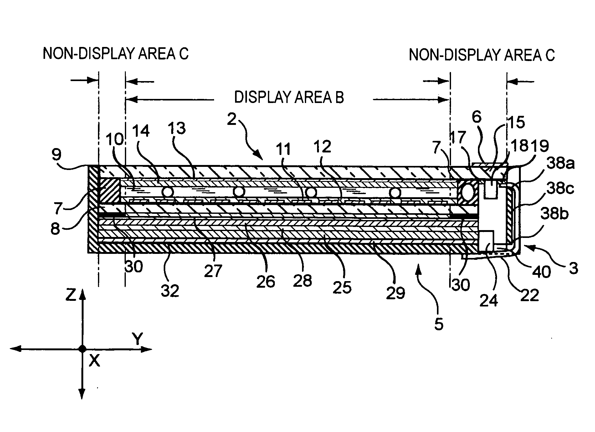
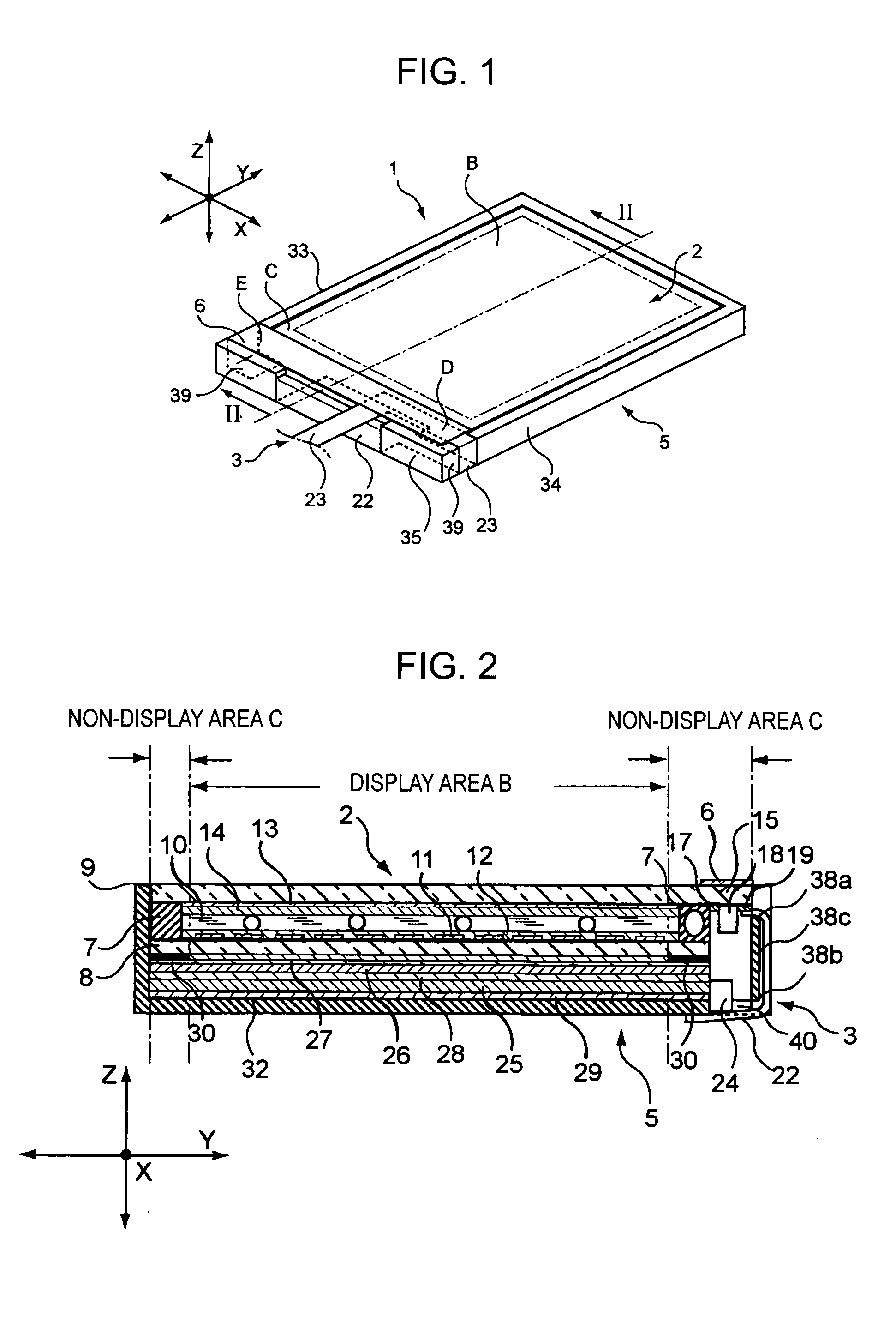
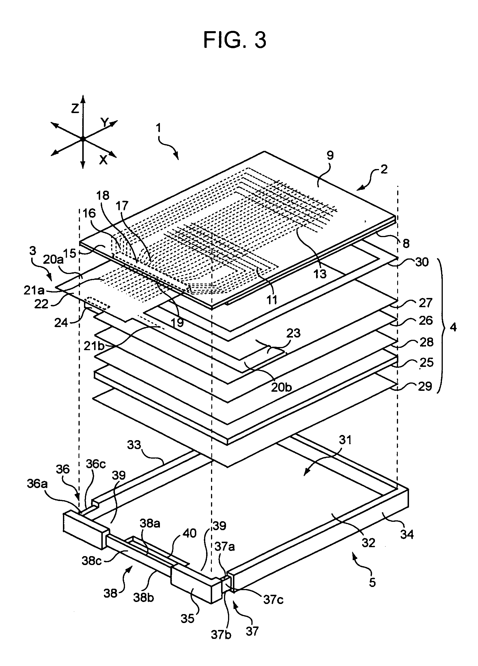
[0041]FIG. 1 is a schematic perspective view of a liquid crystal device according to a first embodiment of the invention. FIG. 2 is a sectional view taken along line II-II shown in FIG. 1 (a liquid crystal driving IC and a light source are not shown in cross section). FIG. 3 is a schematic exploded perspective view of the liquid crystal device.

Structure of Liquid Crystal Device

[0042] As shown in, for example, FIGS. 1 to 3, a liquid crystal device 1 comprises, for example, a liquid crystal panel 2 serving as an electro-optical panel, a flexible board 3 serving as a flexible circuit board electrically connected to the liquid crystal panel 2, an illuminator 4 for illuminating the liquid crystal panel 2 with light, a frame 5 holding the liquid crystal panel 2 and the illuminator 4, and a light-shielding member 6 for intercepting light. Here, supplemental mechanisms (not shown) other than the frame 5 are provided in the liquid crystal device 1 as required.

[0043] As shown in, for exam...

first modification

[0105] A first modification of the first embodiment of the liquid crystal device in accordance with the invention will be described. The first modification differs from the first embodiment in that a light-shielding member is not used and that branches of the flexible board are adhered to respective sides of a frame. Therefore, the modification will be described by focusing on these two points. Parts that are common to those in the first embodiment will be given the same reference numerals and will not be described below.

[0106]FIG. 8 is a schematic perspective view of a liquid crystal device in accordance with the first modification.

[0107] As shown in FIG. 8, a liquid crystal device 101 comprises, for example, a liquid crystal panel 2, a flexible board 103 serving as a flexible circuit board electrically connected to the liquid crystal panel 2, an illuminator 4 (not shown) for illuminating the liquid crystal panel 2 with light, and a frame 5 holding the liquid crystal panel 2 and ...

second modification

[0123] A second modification of the first embodiment of the liquid crystal device in accordance with the invention will be described. The second modification differs from the first embodiment in that a light-shielding member is adhered to both sides of a frame and a flexible board is not adhered to a side surface of the frame. Therefore, the modification will be described by focusing on these two points. Parts that are common to those in the first embodiment will be given the same reference numerals and will not be described below.

[0124]FIG. 9 is a schematic perspective view of a liquid crystal device in accordance with the second modification.

[0125] As shown in FIG. 9, a liquid crystal device 201 comprises, for example, a liquid crystal panel 2, a flexible board 203 serving as a flexible circuit board electrically connected to the liquid crystal panel 2, an illuminator 4 (not shown) for illuminating the liquid crystal panel 2 with light, a frame 5 holding the liquid crystal panel...


PUM

PropertyMeasurementUnit
areaaaaaaaaaaa
adhesionaaaaaaaaaa
flexibleaaaaaaaaaa

Abstract

An electro-optical device includes an electro-optical panel, a frame, and an adhesion base. The panel includes a substrate holding an electro-optical material, a side of the electro-optical panel for displaying an image having a display area and a non-display area. The frame holds the electro-optical panel and has a side wall disposed in correspondence with at least a side surface of the electro-optical panel. An adhesion base has a form extending continuously at least from the non-display area to the side wall and is adhered to the non-display area and the side wall.

Description

BACKGROUND OF THE INVENTION [0001] 1. Technical Field [0002] The present invention relates to an electro-optical device used in, for example, a personal computer or a cellular phone, and to an electronic apparatus using the electro-optical device. [0003] 2. Related Art [0004] Hitherto, an electro-optical device, such as a liquid crystal device, serving as a display device, of an electronic apparatus, such as a personal computer or a cellular phone, has been widely used. [0005] There is a demand for personal computers, cellular phones, etc., to be smaller and lighter and to have a higher resistance to external shock applied when carrying such apparatuses. For the purposes of size reduction and increasing shock resistance, for example, a method which provides a shock-absorbing material having an adhesion portion for being adhered to a liquid crystal panel has been proposed (see, for example, Japanese Unexamined Patent Application Publication No. 2003-308023 (paragraphs 0009 to 0011, a...

Claims


Application Information

Patent Timeline
Patent Type & Authority Applications(United States)
IPC IPC(8): G02F1/13G02F1/1333G06F1/16
CPCG02F1/133308G06F1/1601G02F2202/28G02F1/1333
Inventor MIYAGAWA, SAKIKOKOBAYASHI, SHINICHI
Owner BOE TECH GRP CO LTD
Why Eureka
Try Eureka