Magnet structure

a magnet structure and magnetic field technology, applied in the field of magnet structures, can solve the problems of limited imaging applications, limited application of this design, and insufficient scanning field strength to adequately image the target body parts, etc., and achieve the effect of reducing magnetic reluctan

Inactive Publication Date: 2005-11-29
FONAR
View PDF7 Cites 5 Cited by
  • Summary
  • Abstract
  • Description
  • Claims
  • Application Information

AI Technical Summary

Benefits of technology

[0008]The structural design of the present invention allows for scanning of extremities such as feet, ankles, hands, and wrists, as well as knees, elbows, and upper legs and arms. The structure also can support at least a portion of a patient's body weight, allowing for weight-bearing scans. Accommodation can be made for the patient's leg such that even hips can be scanned.
[0029]A flux collection plate, formed from a magnetic material, such as a ferromagnetic material, is disposed behind each magnetic mass. At least one ferromagnetic conductor connects the flux collection plates, in order to minimize the magnetic reluctance between the permanent magnets.

Problems solved by technology

Conventional extremity scanners, however, have a major drawback in that, due to design constraints, sufficient scanning field strength is not provided to adequately image the target body part.
Typically, the usable field within the gap is provided at a strength of no greater than 0.2 tesla, which may limit some imaging applications.
At least one design provides a larger field strength, but the structural design is such that weight-bearing scans are not possible, so the applications for this design are limited.
Most patients are uncomfortable and become fidgety when confined in this manner, making it more difficult to obtain meaningful diagnostic information.

Method used


Image

  • Magnet structure
  • Magnet structure
  • Magnet structure

Examples


first exemplary embodiment

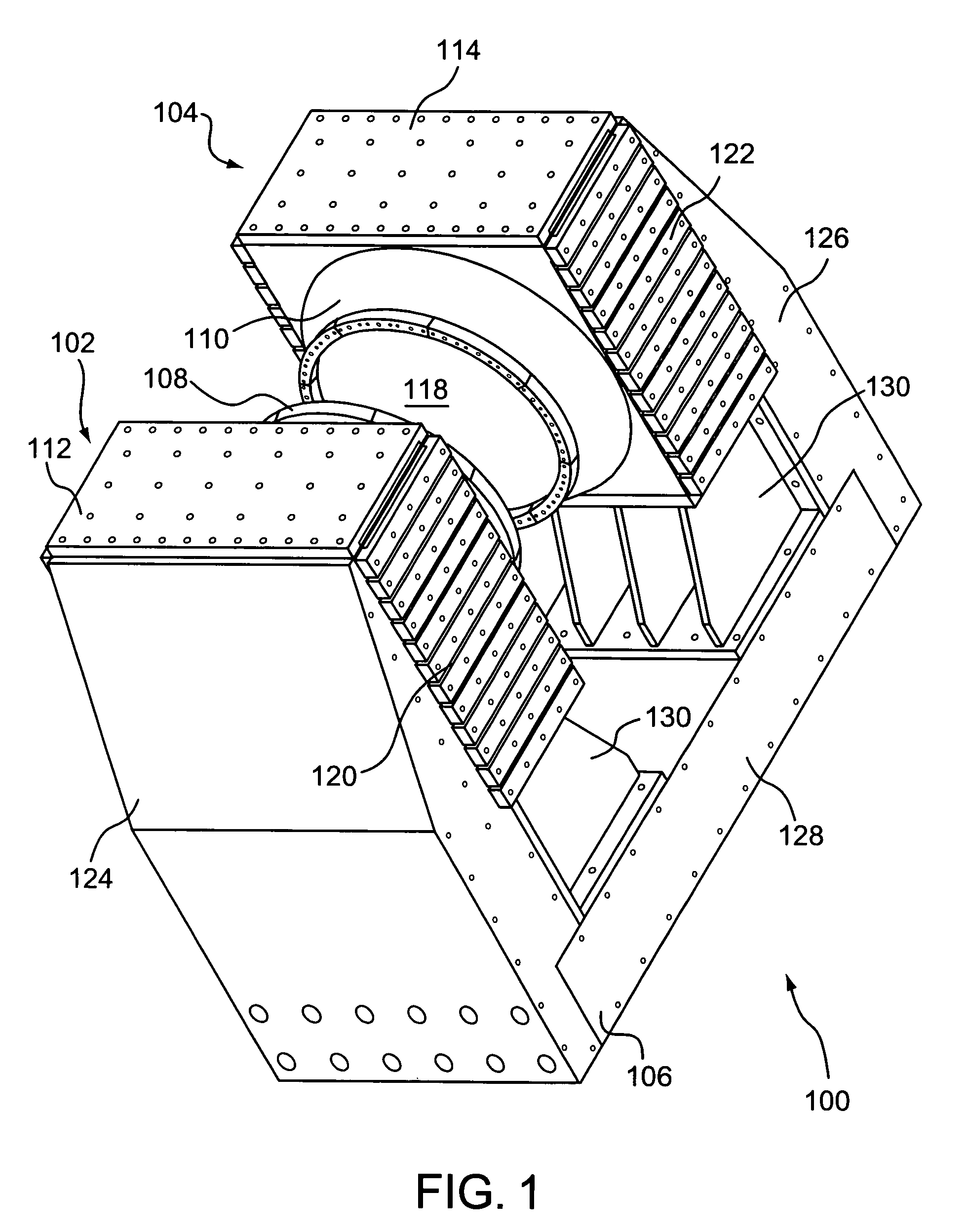
[0057]A first exemplary embodiment of the invention is shown in FIGS. 1–6. FIG. 1 is an isometric view of the magnet structure 100 of this exemplary embodiment. The magnet structure 100 includes a pair of magnet assemblies 102, 104, and a frame 106, which provides support for the first and second magnet assemblies 102, 104 and maintains a fixed distance between them. Although the frame 106 satisfies structural requirements of the magnet structure 100, certain components of the frame 106 can perform functional roles as well.

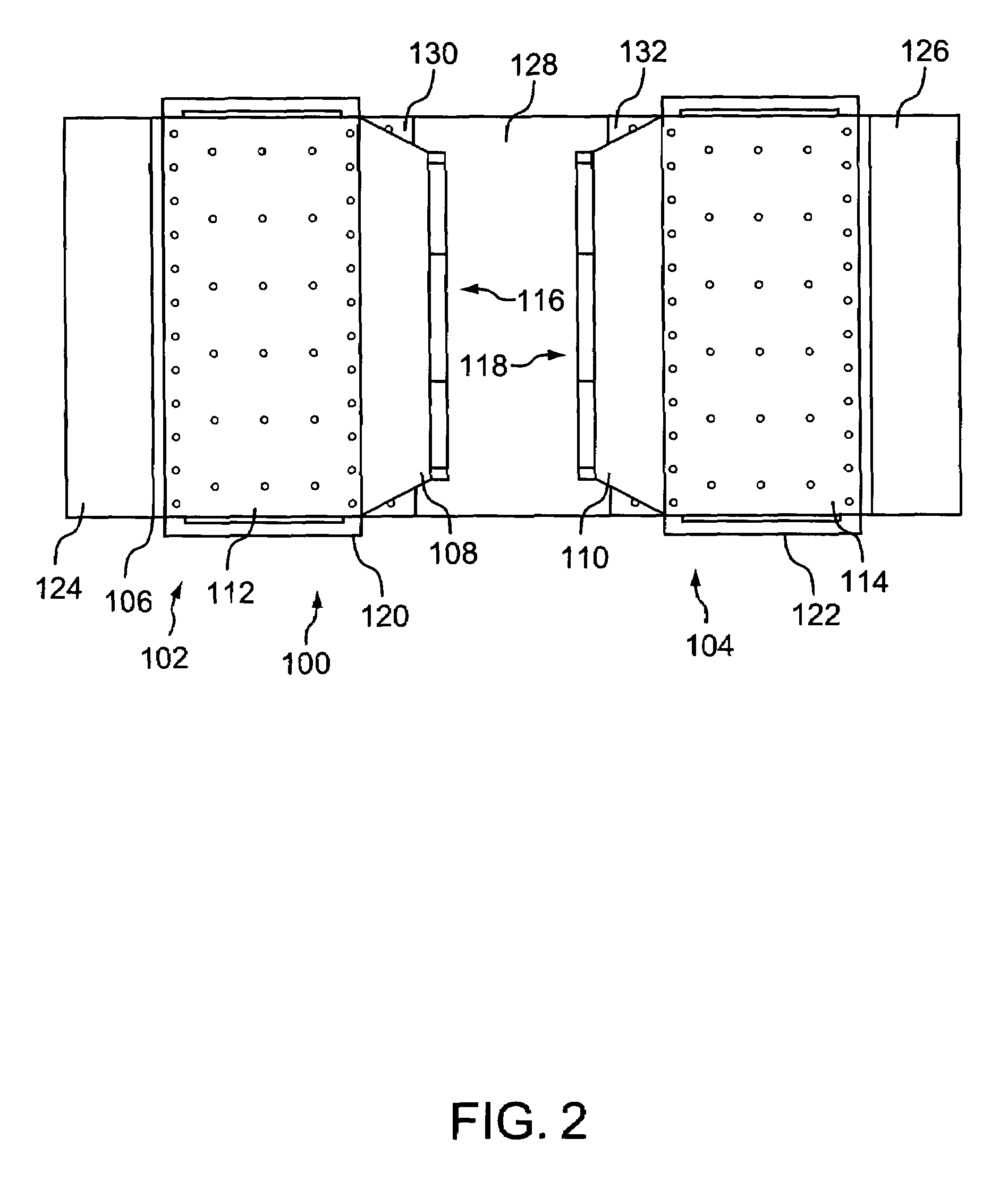
[0058]The first and second magnet assemblies 102, 104 include respective first and second poles 108, 110 and respective first and second magnet enclosures 112, 114. As shown in FIG. 3, the poles 108, 110 are disposed on opposing sides of the magnet enclosures 112, 114, such that faces 116, 118 of the poles 112, 114 are substantially parallel and facing each other. The magnet enclosures 112, 114 are filled with magnetic material, which is the magnetic mass that pro...

second exemplary embodiment

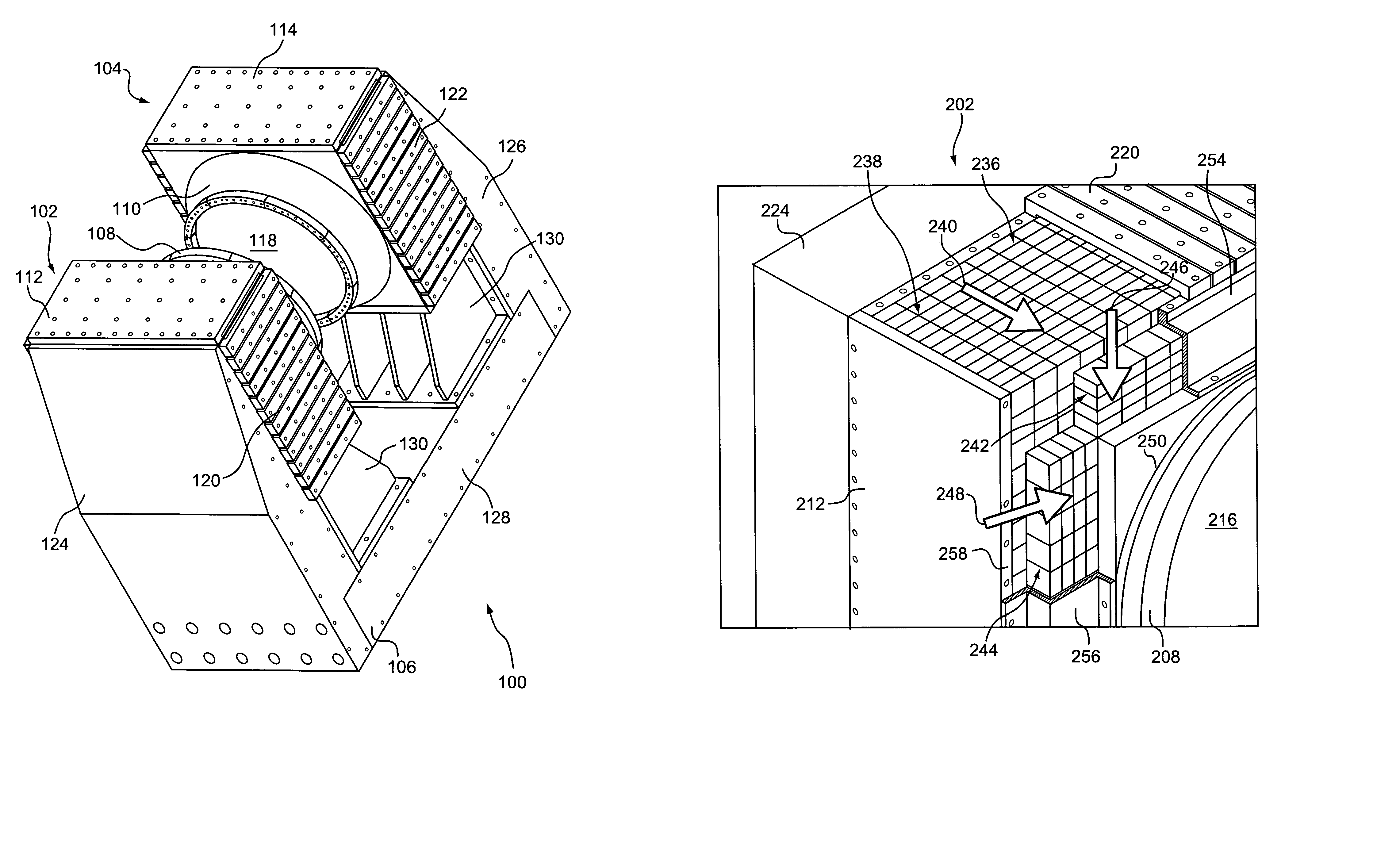
[0062]FIGS. 7–10 illustrate a second exemplary embodiment of the magnet structure 200 of the present invention. As in the first embodiment, the magnet structure 200 includes a pair of magnet assemblies 202, 204, and a frame 206, which provides support for the first and second magnet assemblies 202, 204 and maintains a fixed distance between them. Although the frame 206 satisfies structural requirements of the magnet structure 200, certain components of the frame 206 can perform functional roles as well.

[0063]The first and second magnet assemblies 202, 204 include respective first and second poles 208, 210 and respective first and second magnet enclosures 212, 214. As shown in FIGS. 7 and 8, the poles 208, 210 are disposed on opposing sides of the magnet enclosures 212, 214, such that faces 216, 218 of the poles 208, 210 are substantially parallel and facing each other. The magnet enclosures 212, 214 are filled with magnetic material, which is the magnetic mass that provides the magn...

third exemplary embodiment

[0072]A third exemplary embodiment of the present invention is shown in FIGS. 11–15. As shown in FIG. 11, the magnet structure 300 includes first and second opposing permanent magnet assemblies 302, 304, held in place and separated by a frame 306. The frame includes first and second frame ends 308, 310, to which the magnet assemblies 302, 304 are attached. The frame ends 308, 310 are separated by a number of spacers 312, which keep the opposing poles 314, 316 apart by a selected distance so as to form a gap therebetween that is suitable for the intended use of the magnet structure 300.

[0073]As shown in FIG. 12, each frame end 308, 310 is formed in the shape of a cross, that is, consisting of connected, transverse, or intersecting pieces forming a construction having four segments emanating from a common point, such that the segments are arranged at substantially right angles with respect to adjacent segments. Thus, the exemplary embodiment shown in FIGS. 11–14 utilizes frame ends ha...


PUM

PropertyMeasurementUnit
atomic numbersaaaaaaaaaa
thickaaaaaaaaaa

Abstract

A magnet structure produces a field within a magnet gap. The field is provided at least in part by a pair of permanent magnets that are fixed in place by a frame. The frame fixes a magnet assembly that is adapted to hold the magnetic material composing the permanent magnets, such that the quantity of the magnetic material can be adjusted to suit the particular application. The magnetic material can be provided in the form of discrete magnetic elements, such as magnetic “bricks”. The frame also functions as the flux collector and return. Accordingly, the general geometry of the magnet structure is fixed, and the amount of magnetic material, and therefore the magnetic field strength, is adjustable.

Description

CROSS-REFERENCE TO RELATED APPLICATIONS[0001]This is a continuation of co-pending U.S. patent application Ser. No. 09 / 998,907, which was filed on Nov. 23, 2001, and which in turn was based on U.S. Provisional Patent Application Ser. No. 60 / 252,422, filed on Nov. 22, 2000, which is incorporated herein in its entirety.FIELD OF THE INVENTION[0002]The present invention relates to magnet structures. In particular, the present invention relates to structures of magnets to be used for nuclear magnetic resonance imaging.BACKGROUND OF THE INVENTION[0003]Nuclear magnetic resonance imaging (“MRI”) is utilized for scanning and imaging biological tissue as a diagnostic aid, and is one of the most versatile and fastest growing modalities in medical imaging. As part of the MRI process, the subject patient is placed in an external magnetic field. This field is created by a magnet assembly, which may be closed or open. Open magnet assemblies have two spaced-apart magnet poles separated by a gap, and...

Claims


Application Information

Patent Timeline
Patent Type & Authority Patents(United States)
IPC IPC(8): G01R33/383H01F1/00H01F7/02
CPCG01R33/383H01F7/0278
Inventor DANBY, GORDONJACKSON, JOHNDAMADIAN, RAYMONDWAHL, WILLIAM H.TENORE, ANTHONY
Owner FONAR
Why Eureka
Try Eureka