Intraoral device

a technology of intraoral devices and mouthpieces, which is applied in the field of dental appliances, can solve the problems of difficult illumination of the interior of the mouth of a dental patient during dental examination and/or operation, limited amount of light entering the oral cavity using this type of lighting, and limited light directed only on a limited area in the mouth

Inactive Publication Date: 2005-12-13
INNERLITE
View PDF28 Cites 69 Cited by
  • Summary
  • Abstract
  • Description
  • Claims
  • Application Information

AI Technical Summary

Benefits of technology

[0007]An aspect of the invention involves a one-piece, injection-molded intraoral device. The intraoral device includes a one-piece, flexible, injection molded body made of a single homogeneous material. The body includes an upper front flap including an upper edge, an upper rear flap including an upper edge separated from the upper edge of the upper front flap by a gap, a lower front flap including a lower edge, and a lower rear flap including a lower edge separated from the lower edge of the lower front flap by a gap. The upper edges of the front flaps are configured to be sealed by an upper part of a patient's mouth and form an upper evacuation channel when the body is disposed within the patient's mouth. The lower edges of the lower flap are configured to be sealed by a lower part of a patient's mouth and form a lower evacuation channel when the body is disposed within the patient's mouth. One or more evacuation holes in at least one of the upper flaps are in communication with the upper evacuation channel and one or more evacuation holes in at least one of the lower flaps are in communication with the lower evacuation channel. A connection section is in communication with the upper evacuation channel and the lower evacuation channel and is configured to extend outside of the patient's mouth to connect with a vacuum source for evacuating fluid from the patient's mouth through the evacuation holes and the evacuation channels.
[0008]Another aspect of the invention involves a one-piece, injection-molded intraoral device. The intraoral device includes a one-piece, flexible, injection molded body made of a single homogeneous material. The body includes a flexible upper portion that contacts an upper part of the patient's mouth when the body is disposed within the mouth of the patient and a flexible lower portion that contacts a lower part of the patients mouth when the body is disposed within the mouth of the patient. One or more evacuation holes are in at least one of the upper portion and the lower portion, and one or more evacuation channels are in communication with the one or more evacuation holes. A connection section is in communication with the one or evacuation channels and configured to extend outside of the patient's mouth to connect with a vacuum source for evacuating fluid from the patient's mouth through the one or more evacuation holes and the one or more evacuation channels. A flexible bite piece of the intraoral device is vertically compressible, longitudinally displaceable, and laterally displaceable.
[0009]A further aspect of the invention involves a vacuum-only adapter for connecting a vacuum source without illumination capability to an intraoral illumination device. The intraoral illumination device includes a body that is inserted within a patient's mouth. The body includes one or more evacuation holes in communication with one or more evacuation channels to remove fluid from the patient's mouth. An illumination member of the intraoral illumination device illuminates an interior of the patient's mouth. A bite piece of the intraoral illumination device is engaged by a patient's teeth to hold the body in place within the patient's mouth. A connection section of the intraoral illumination device includes an illumination connector that is optically coupled to the illumination member and a vacuum connector that is in communication with the one or more evacuation channels. The vacuum-only adapter includes a plug portion configured to be matingly received by the connection section, a handling portion extending proximally from the plug portion and configured to be handled by a patient, a plug extending distally from the plug portion and configured to mate with the illumination connector to plug the illumination connector, and one or more vacuum lumens carried by the plug portion to communicate with the vacuum connector channels to remove fluid from the patient's mouth.
[0010]Other, more particular features and advantages of the inventions are set forth in the following detailed description and drawings.

Problems solved by technology

Illuminating the interior of a dental patient's mouth during dental examination and / or operation is difficult because the patient's mouth must be illuminated through a narrow opening, i.e., the patient's mouth, and the dentist must work in close proximity to the mouth, often blocking the light source.
The amount of light entering the oral cavity using this type of lighting is somewhat limited due to the fact that the light source is remote from the patient's mouth.
However, this type of lighting has a number of drawbacks.
Light is only directed on a limited area in the mouth and does not provide illumination for the entire oral cavity.
Additionally, the presence of this type of lighting, typically as an add-on feature on the instrument interferes with the comfortable and proper use of the instrument.
Other devices have been designed specifically for illuminating a patient's teeth, but these devices suffer from any or all of the following drawbacks: inadequate illumination of the patient's teeth, and interference with other dental instruments used during the examination and / or operation.

Method used


Image

  • Intraoral device
  • Intraoral device
  • Intraoral device

Examples


Embodiment Construction

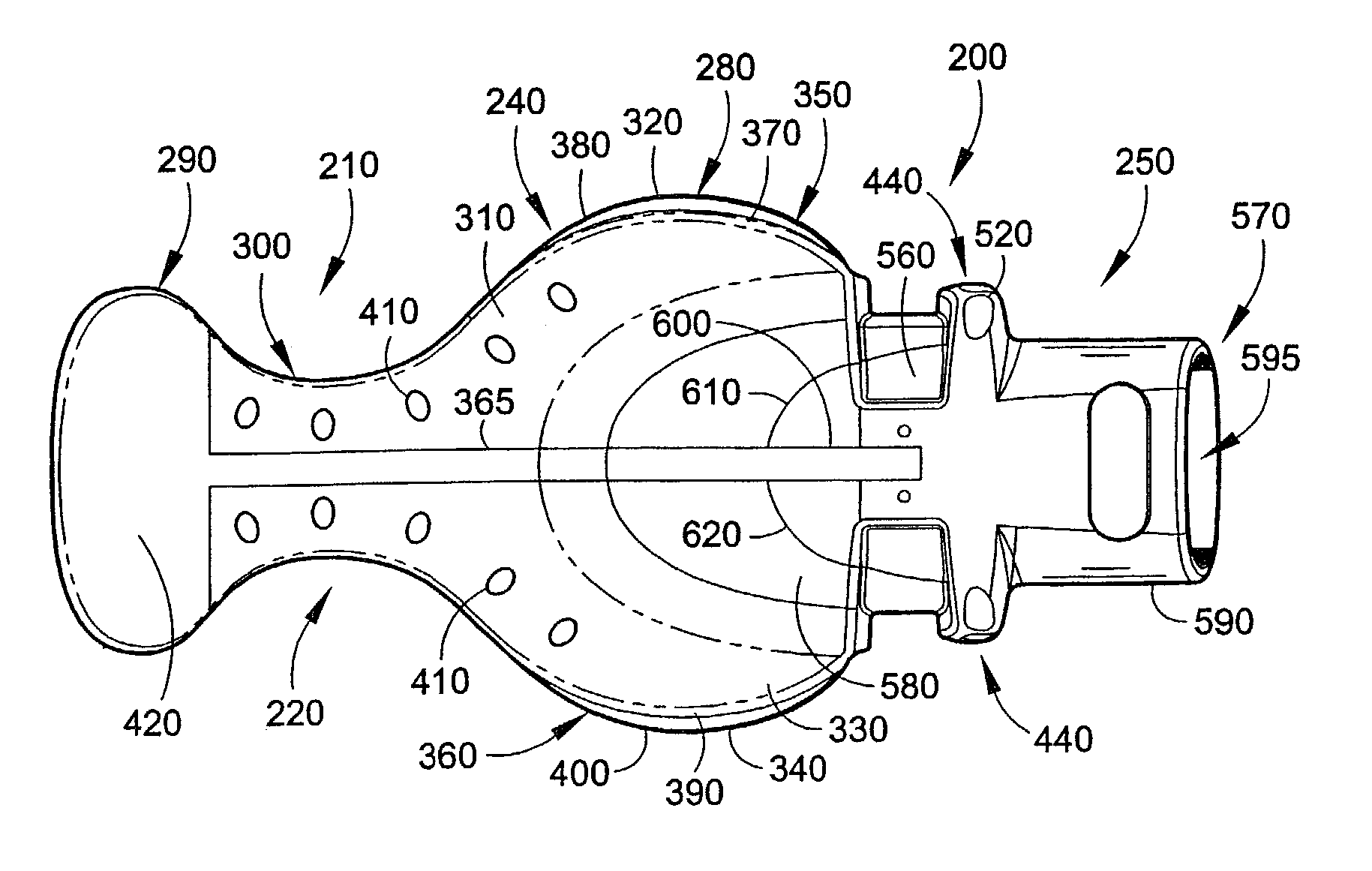
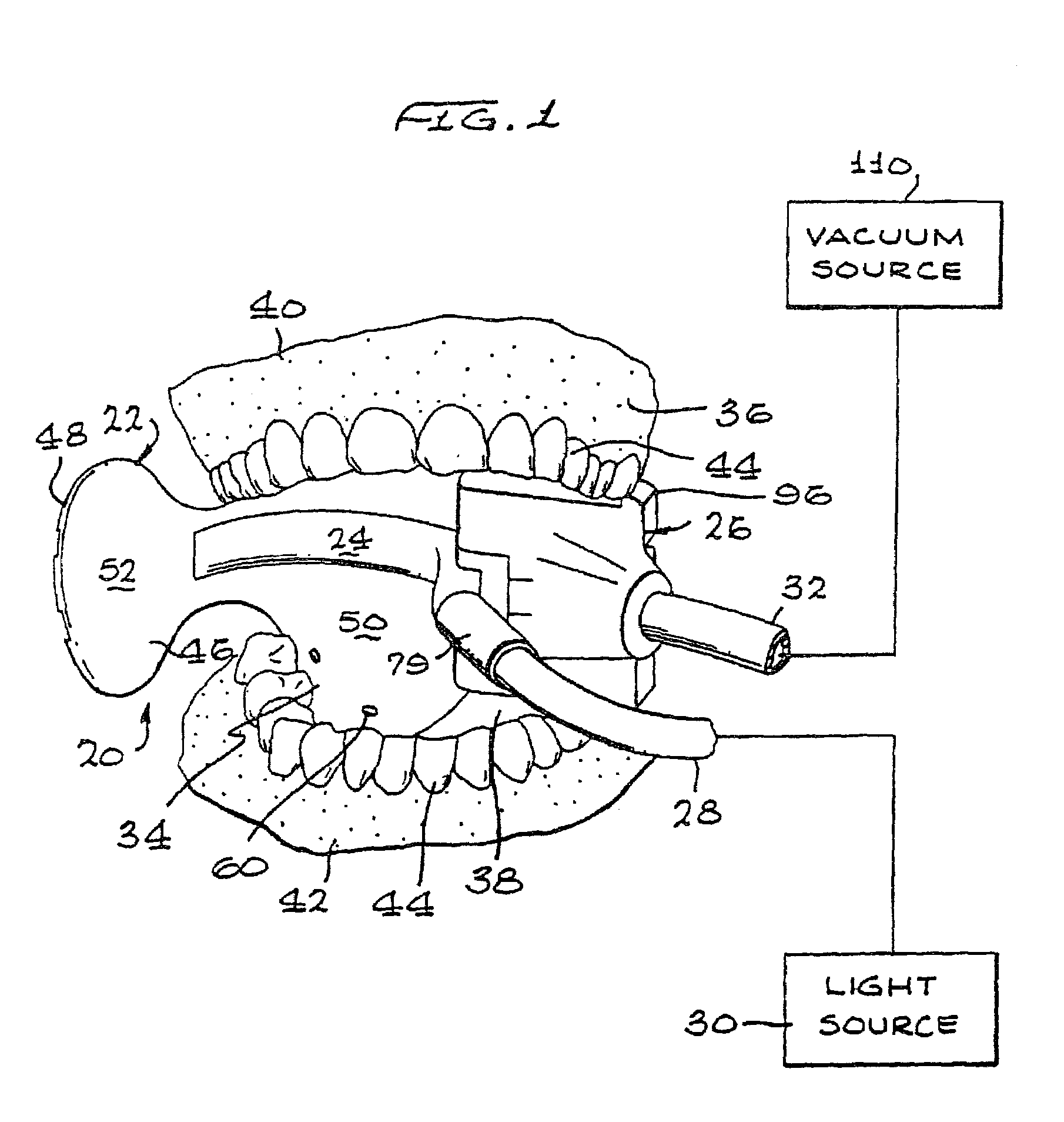
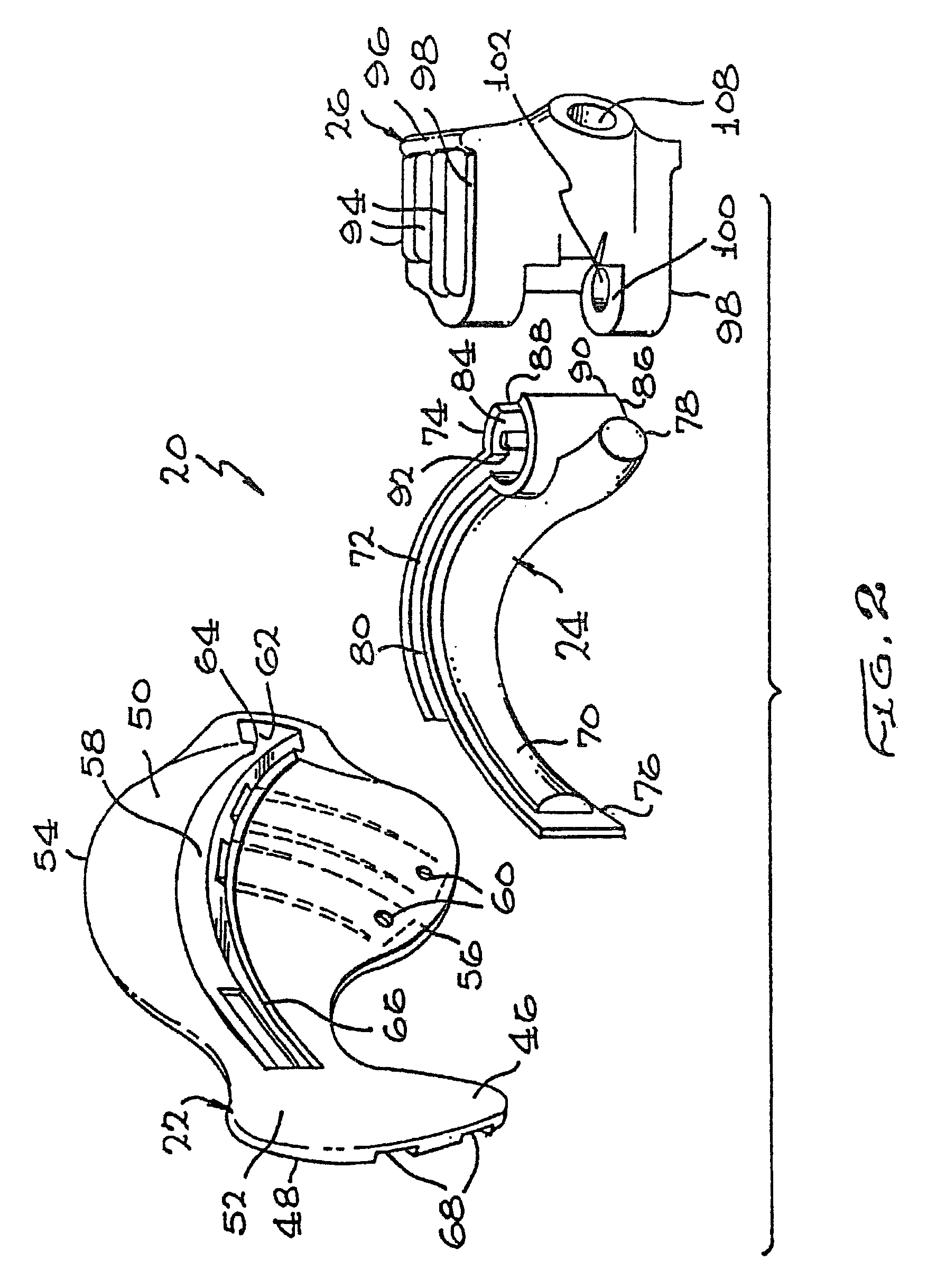
[0042]With reference to FIGS. 1 and 2, a preferred embodiment of an intraoral illumination device, indicated generally by the reference numeral 20, will now be described. The intraoral illumination device 20 generally includes a tongue and cheek retractor 22, a dispersion piece 24, and a bite block or piece 26. The tongue and cheek retractor 22 is a disposable piece, and the dispersion piece 24 and bite piece 26 are sterilizable for reuse. The dispersion piece 24 is coupled to a light carrier such as a fiber optic bundle 28 and extraoral light source 30 for illuminating the dispersion piece 24. A fluid evacuation tube 32 is in communication with the bite block 26 and a fluid evacuation system 34 of the device 20 for evacuating fluids from a patient's mouth 36.

[0043]The intraoral illumination device 20 will now be described generally in use. The patient opens his or her mouth 36 and a health care provider inserts the device 20 into an intraoral cavity 38 of the patient's mouth 36 bet...


PUM


Abstract

An intraoral device includes a one-piece, flexible, injection molded body made of a single homogeneous material. The body includes upper front and rear flaps, and lower front and rear flaps. Upper edges of the front flaps and lower edges of the lower flaps are sealed by respective upper and lower parts of a patient's mouth to form upper and lower evacuation channels when the body is disposed within the patient's mouth. Evacuation holes in the flaps are in communication with the evacuation channels. A connection section is in communication with the evacuation channels and is configured to extend outside of the patient's mouth to connect with a vacuum source for evacuating fluid from the patient's mouth through the evacuation holes and the evacuation channels.

Description

CROSS-REFERENCE TO RELATED APPLICATIONS[0001]This is a continuation-in-part of prior application Ser. No. 10 / 006,732 filed Nov. 15, 2001, which issued on Jun. 10, 2003 as U.S. Pat. No. 6,575,746, which is a continuation of prior application Ser. No. 09 / 777,491 filed Feb. 05, 2001 which issued on Jan. 15, 2002 as U.S. Pat. No. 6,338,627, which is a continuation of prior application Ser. No. 09 / 490,923 filed on Jan. 25, 2000, now abandoned, which is a continuation of prior application Ser. No. 09 / 193,916 filed on Nov. 17, 1998, which issued on Feb. 8, 2000 as U.S. Pat. No. 6,022,214.FIELD OF THE INVENTION[0002]The invention relates, in general, to dental appliances, and, in particular, to dental appliances for illuminating and / or vacuum suction of the mouth of a dental patient for examination and / or operative purposes.BACKGROUND OF THE INVENTION[0003]Illuminating the interior of a dental patient's mouth during dental examination and / or operation is difficult because the patient's mout...

Claims


Application Information

Patent Timeline
Patent Type & Authority Patents(United States)
IPC IPC(8): A61C17/06A61C17/08A61C17/14
CPCA61C5/14A61C17/043A61C17/04A61C5/90A61C17/08A61C17/084A61C17/10A61C17/12A61C1/088
Inventor HIRSCH, JAMES A.HIRSCH, THOMAS R.
Owner INNERLITE
Why Eureka
Try Eureka