Vehicular header console system

a console system and headlight technology, applied in the field of vehicle headlight display system, can solve the problems of little to no aid to a driver or other person, and the tire pressure monitoring sensor does not provide a readily readable indication of correct or incorrect tire inflation pressure to the person

Inactive Publication Date: 2005-12-13
DONNELLY CORP
View PDF27 Cites 196 Cited by
  • Summary
  • Abstract
  • Description
  • Claims
  • Application Information

AI Technical Summary

Benefits of technology

[0005]The present invention provides a new and useful system that provides an indicator external of the vehicle to indicate the inflation condition of the vehicle tires. The present invention provides a readily interpretable indication of correct or incorrect tire inflation pressure to a person external to the vehicle who is adjusting the tire pressure in that tire on the vehicle, and especially while that person is in the act of adjusting that tire pressure. Preferably, the indicator is positioned at an exterior vehicle portion, such as a vehicle exterior rearview mirror assembly, where the indicator can be observed by a user inflating or deflating the vehicle tires located at the vehicle side of that exterior vehicle portion. However, the present invention may also be used as a convenient indicator to the driver or passenger entering a vehicle that one or more of the vehicle tires are in an under-pressure or over-pressure condition.

Problems solved by technology

While such displays alert the driver of the vehicle sitting in the interior vehicular cabin when the vehicle is operating as to the inflation status of individual tires present on the vehicle, they are little to no aid to a driver or other person while actually pumping air into or bleeding air from an individual tire in response to recognition of an undesired tire inflation pressure.
Thus, even though the vehicle tire may be equipped with a sensor for measuring the air pressure in the tire, in systems known to date, this tire pressure monitoring sensor does not provide a readily readable indication of correct or incorrect tire inflation pressure to the person external to the vehicle who is adjusting the tire pressure in that tire on the vehicle, and especially while that person is in the act of adjusting that tire pressure.

Method used


Image

  • Vehicular header console system
  • Vehicular header console system
  • Vehicular header console system

Examples


Embodiment Construction

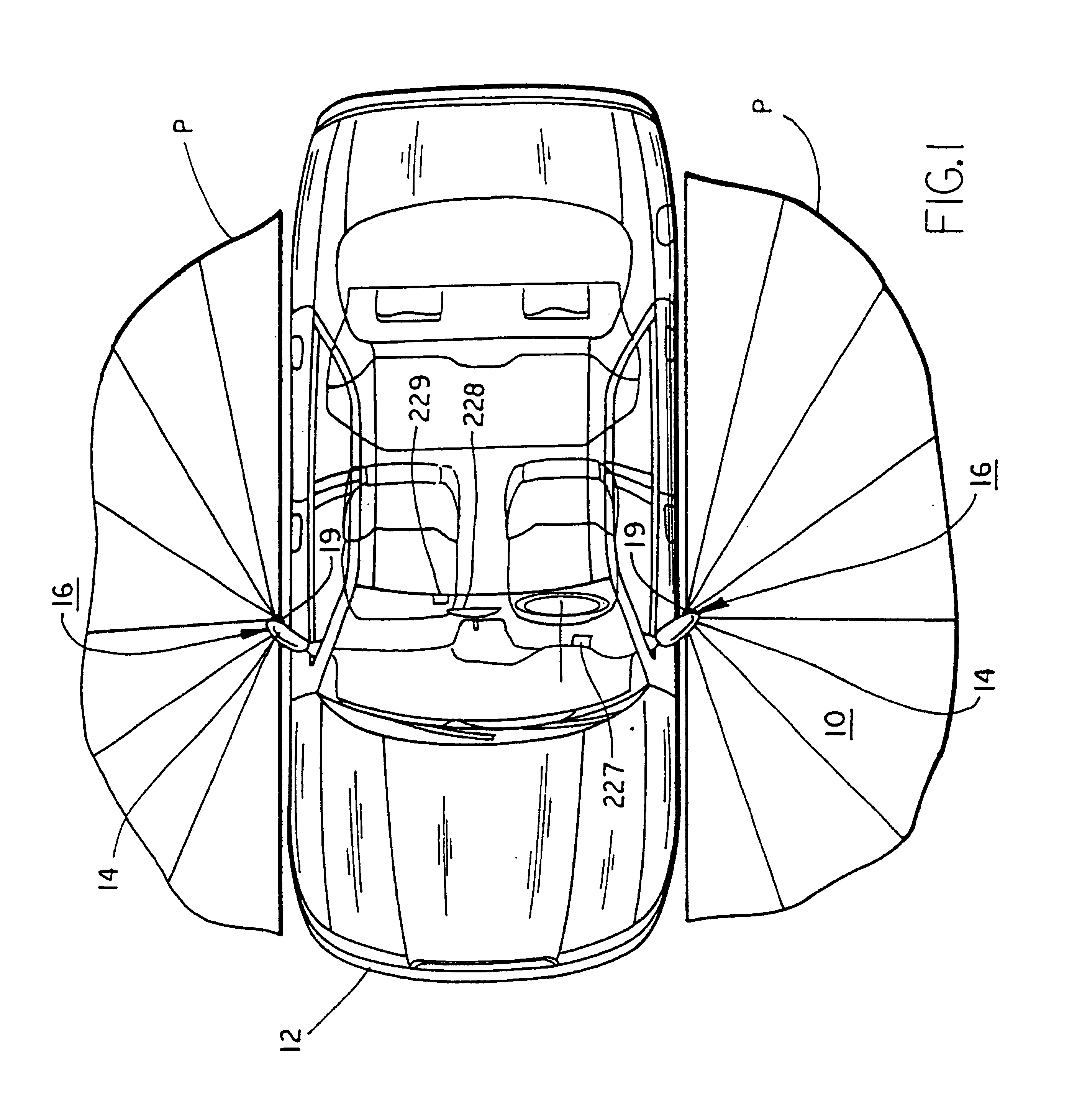
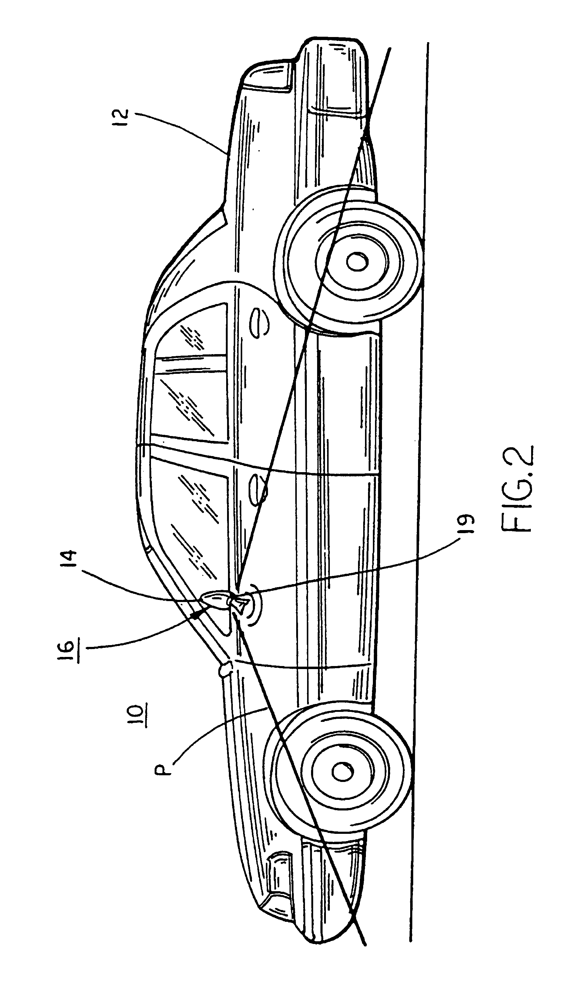
[0042]Referring now specifically to the drawings, and the illustrative embodiments depicted therein, a vehicle exterior rearview mirror system 10 for use with vehicle 12 includes one or more exterior rearview mirror assemblies 14 and a tire inflation monitoring system 16 (FIGS. 1, 2 and 6). Tire inflation monitoring system 16 includes at least one tire pressure indicator assembly 19 positioned at exterior rearview mirror assembly 14, a control 18, and one or more tire pressure sensors 20, each associated with one of the vehicle tires. Each tire pressure sensor 20 is connected wirelessly with control 18 by a wireless communication link 22 that, in the illustrated embodiment, is a radio frequency (RF) link. Tire pressure sensor 20 is commercially available from several sources and conventionally includes a wireless communication link 22 with a vehicle controller. Control 18 is an electronic control, and is preferably a microprocessor-based electronic control, but may, alternatively, b...


PUM


Abstract

An improved header console system suitable for use in an interior cabin of a vehicle including a header console assembly, with a headliner portion disposed at the roof of the interior cabin of the vehicle and a windshield portion extending from the headliner, with the windshield portion provided at the windshield. In addition, the windshield portion includes at least one vehicle accessory.

Description

CROSS-REFERENCE TO RELATED APPLICATION[0001]This application is a continuation application of U.S. patent application Ser. No 09 / 710,016, filed Nov. 10, 2000, now U.S. Pat. No. 6,445,287, issue date Sep. 3, 2002, which is a continuation-in-part of U.S. co-pending Pat. application entitled TIRE INFLATION ASSISTANCE MONITORING SYSTEM, Ser. No. 09 / 513,941, filed Feb. 28, 2000, now U.S. Pat. No. 6,294,989, which is incorporated by reference herein in its entirety.BACKGROUND OF THE INVENTION[0002]This invention relates generally to vehicular function monitoring and display systems. More particularly, the invention is related to a system for assisting the manual inflating of tires while mounted on the wheels of a vehicle. Most particularly, this invention is related to a system for assisting the manual inflating of tires of the vehicle that includes an indicator assembly positioned on an exterior vehicle portion such as an exterior mirror assembly.[0003]Remote tire pressure sensors have b...

Claims


Application Information

Patent Timeline
Patent Type & Authority Patents(United States)
IPC IPC(8): B60C23/00B60C23/04B60Q1/26B60R1/12G02B6/00G02B27/00
CPCB60C23/00B60C23/0401B60C23/0406B60C23/0408B60Q1/2665B60R1/12H04N5/2253G06F17/00B60R11/04G02B6/00G02B2027/0118G02B2027/012B60R1/1207B60Q1/2661B60R1/02
Inventor SCHOFIELD, KENNETHLYNAM, NIALL R.
Owner DONNELLY CORP
Why Eureka
Try Eureka