Eureka AIR delivers breakthrough ideas for toughest innovation challenges, trusted by R&D personnel around the world.

Portable electrical device with planar antenna

Active Publication Date: 2005-12-27
ASUSTEK COMPUTER INC
View PDF9 Cites 13 Cited by
  • Summary
  • Abstract
  • Description
  • Claims
  • Application Information

AI Technical Summary

Benefits of technology

[0007]The present invention discloses a notebook computer being capable of transmitting and receiving data via an antenna hidden and built in the housing of a display of the notebook computer. The notebook computer comprises the following components. A display panel is contained and assembled in a panel housing. There is a reserved space, generally with a height less than 1.5 cm, left between the top edge of the display panel and the inner surface of the panel housing. A planar antenna made of a bar-shaped circuit board and having a width of 1.0˜1.4 cm is disposed upright standing on the top edge of the display panel. The planar antenna is just contained in the reserved space between the display panel

Problems solved by technology

However, wired networks are relatively expensive in design and layout, and construction and wiring of the wired networks frequently cause damage to rented office buildings, and densely spread wire lines are too complicated to manage and maintain.
Therefore, it is inconvenient for users to carry the antenna device 14 and cable line 16 with the notebook 10 simultaneously when they want to utilize the wireless network function of the notebook 10 in different places.
And further, it is required to fabricate connectors on the two ends of the cable line for connecting with the network card, thereby increasing the prime cost thereof.

Method used


Image

  • Portable electrical device with planar antenna
  • Portable electrical device with planar antenna
  • Portable electrical device with planar antenna

Examples


third embodiment

[0019]Then, please refer to FIG. 4, in the present invention, the planar antenna 70 is fabricated on one lateral edge (right or left side) of the display panel 542 and contained in the space between the display panel 542 and the housing 541. It is noted that, though in FIG. 4, the planar antenna 70 is attached onto the lateral edge of the display panel 542, however, in actual practice, the planar antenna 70 can also be mounted to hang or stand aside the display panel 542.
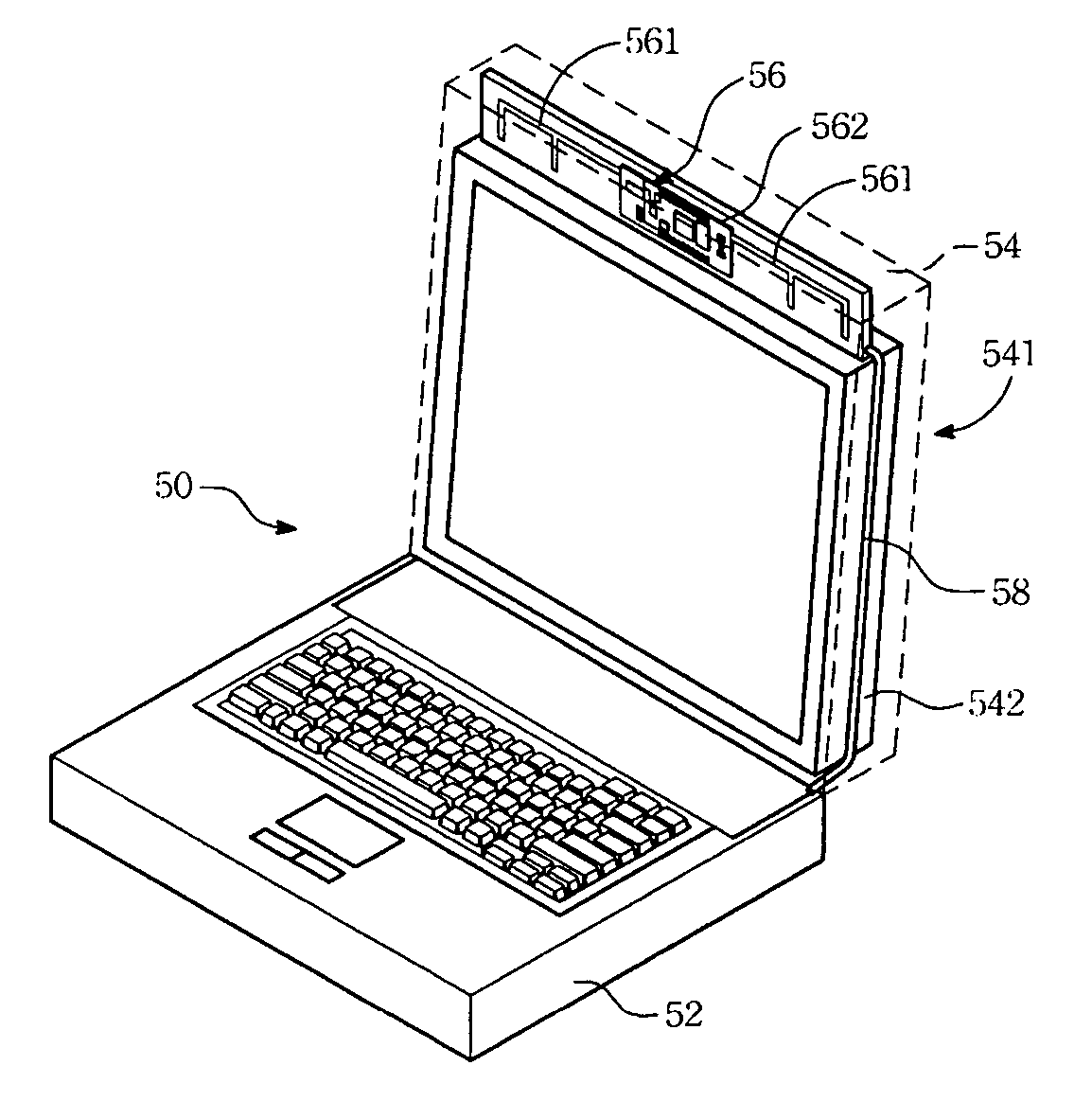
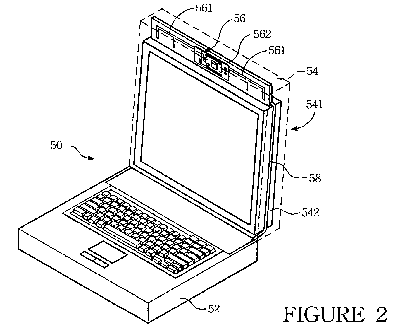
first embodiment

[0020]The design of fabricating the planar antenna onto the display panel disclosed in the present invention has following advantages: (1) because the planar antenna and the transmitting line both are assembled in the panel housing, the problems of careless bump or stumble to cause the antenna damaged are effectively avoided. (2) In the first embodiment, there is no need to increase the thickness of the panel housing because the planar antenna is mounted on the top edge of the display panel, thereby satisfying the current design requirements of less weight and smaller size. (3) The planar antenna is mounted directly onto the display panel, so the ground lines on the display panel can also be used to remove the accumulated ions on the planar antenna. (4) Because the current motherboard is fabricated with 4˜8 sets of USB connectors thereon, the transmitting line of the present invention extending to the host case can connect to the USB connectors formed on the motherboard directly. Th...


PUM


Abstract

A portable electrical device with a planar antenna for wireless transmitting data includes a host case for assembling a motherboard therein and a display module pivotally connected to the host case. The display module has a housing for containing a display panel and the planar antenna. The planar antenna is connected to the motherboard via a transmitting line for transmitting and receiving the signals to and from the planar antenna.

Description

FIELD OF THE INVENTION[0001]The present invention relates to a portable electrical device with an antenna device, and more particularly, to a design of fabricating a PCB antenna onto the edge of the display panel of a notebook.BACKGROUND OF THE INVENTION[0002]With rapid development and progress of electronic technology, notebooks of a new generation provide a powerful operation function and are widely used in a company and personal consumers. Moreover, local networks are constructed in most of companies or industries by installing cables and servers so as to effectively connect those notebooks and communicate or exchange various information and data. However, wired networks are relatively expensive in design and layout, and construction and wiring of the wired networks frequently cause damage to rented office buildings, and densely spread wire lines are too complicated to manage and maintain. Therefore, wireless networks have been used in many companies or industries to construct th...

Claims


Application Information

Patent Timeline
IPC IPC(8): G06F1/16H01Q1/24H01Q1/38
CPCG06F1/1616G06F1/1637H01Q1/241H01Q1/38
Inventor SUN, JELLENTDENG, TEN-LONG
Owner ASUSTEK COMPUTER INC
Why Eureka
Eureka Blog
Learn More