
Embroidering system

a technology of embroidering machine and embroidering machine, which is applied in the direction of embroidering machine, automatic machine, textiles and paper, etc., can solve the problem that the above-described embroidering machine is stopped from operating

Inactive Publication Date: 2005-12-27
AISIN SEIKI KK
View PDF5 Cites 30 Cited by
  • Summary
  • Abstract
  • Description
  • Claims
  • Application Information

AI Technical Summary

Benefits of technology

The present invention is about an embroidering system that includes a control device and an embroidering machine with multiple needles. The control device generates and stores embroidery data that is sent to the embroidering machine to selectively drive the needles. The embroidery data is corrected as required and is based on the needle numbers and thread colors. The system selects the thread color that is closest to the color specified in the embroidery data, if the thread colors do not correspond to the specified color. The control device can be physically separated from the embroidering machine. The technical effect of this invention is to improve the accuracy and efficiency of embroidering by automatically selecting the correct thread color based on the embroidery data and correcting the data as required.

Problems solved by technology

However, the above-described embroidering machine is stopped from operation every time when the currently supplied thread is changed to another thread with the specified color.

Method used


Image

  • Embroidering system
  • Embroidering system
  • Embroidering system

Examples


Embodiment Construction

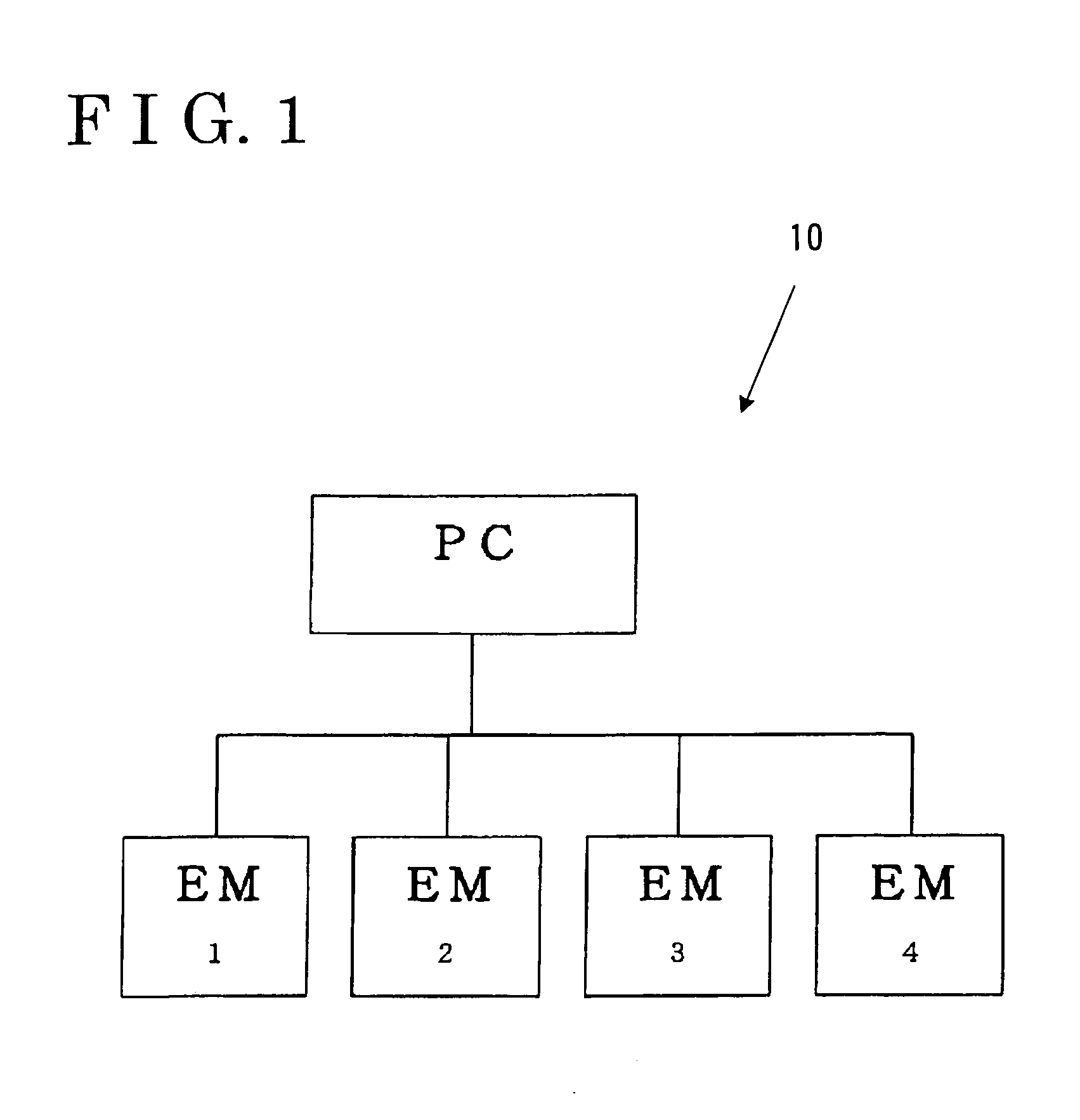
[0013]As illustrated in FIG. 1, an embroidery system 10 according to an embodiment of the present invention includes a personal computer PC, i.e., a control device, connected to at least one embroidering machine EM. The personal computer PC according to the embodiment of the present invention is connected to four embroidering machines EM. The four embroidering machines EM are operatively driven based upon an embroidery data from the personal computer PC all together at a time or with a predetermined time gap therebetween.

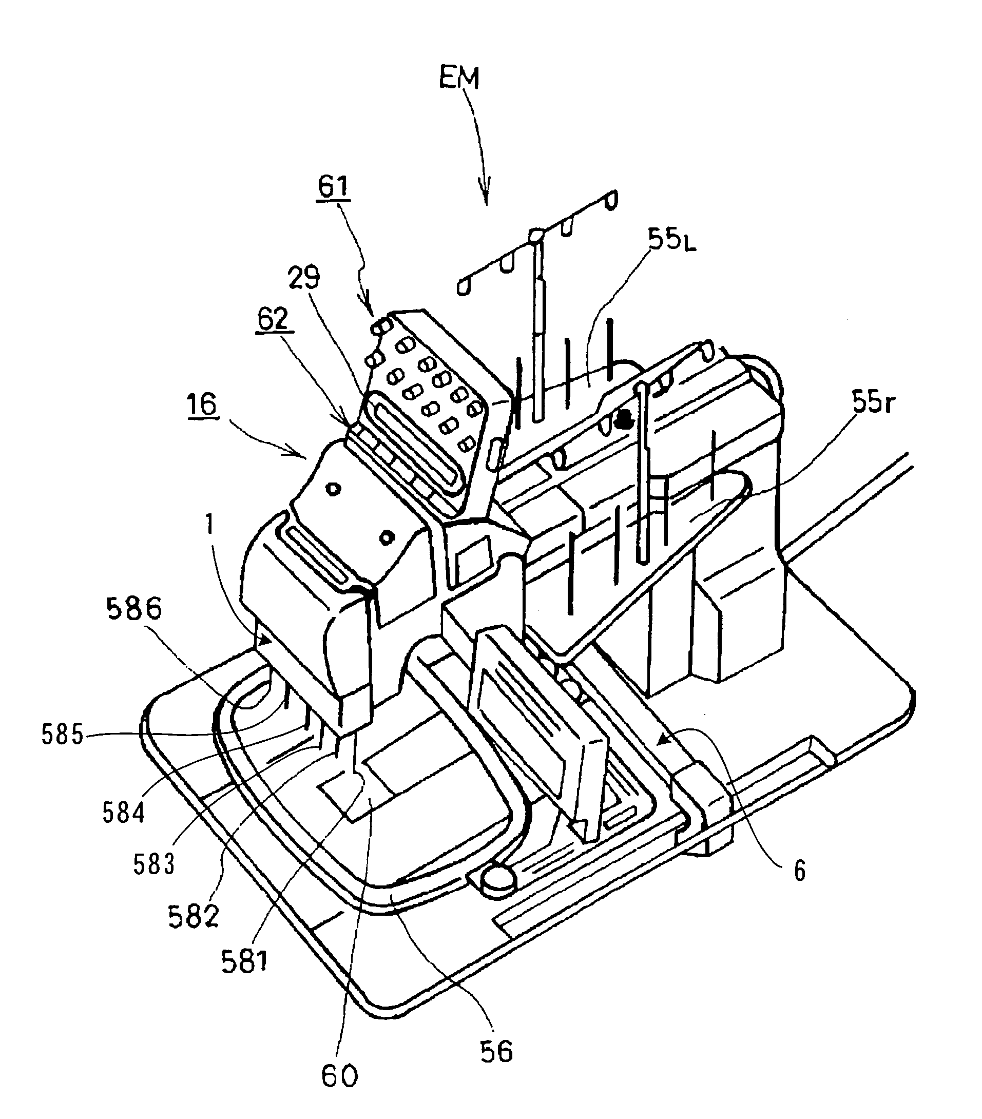
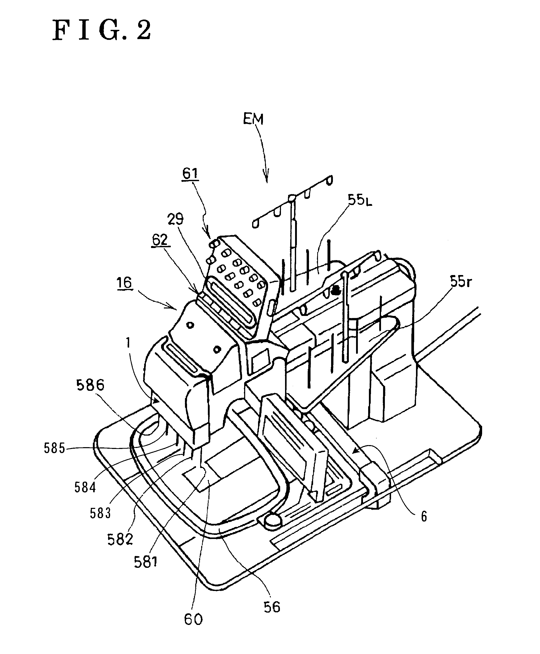
[0014]Explaining one of the embroidering machines EM with reference to FIG. 2, the embroidering machine EM is provided with an embroidery frame driving mechanism 6 for driving a known embroidery frame 56 at a horizontal plane in one of directions of axis and Y-axis, a known embroidering mechanism 1 for reciprocating a needle over a center hole 60, and a needle selector 16 of which equivalents are disclosed in Japanese Examined Patent Application Publication No. 53(1...


PUM


Abstract

An embroidering system includes at least one embroidering machine having plural needles supplied with threads having different colors, and a control device for transmitting an embroidery data to the at least one embroidering machine so as to selectively drive the plural needles. The embroidery data is generated and memorized in the control device prior to being transmitted to the at least one embroidering machine. The embroidery data is corrected as required. It is preferable that the embroidery data is corrected as the basis for needle numbers for the respective needles and the colors of the threads supplied to the respective needles.

Description

[0001]This application is based on and claims priority under 0.35 U.S.C. 119 with respect to Japanese Patent Application 2002-299336, filed on Oct. 11, 2002, the entire content of which is incorporated herein by reference.FIELD OF THE INVENTION[0002]This invention generally relates to an embroidering machine with plural needles selectively driven in response to command from an operating unit.BACKGROUND[0003]Conventionally, an embroidering chine, which is provided with plural needles for embroidering a work piece, has been widely known. The plural needles are alternately operated in response to commands from an operating unit. The embroidery machine can thus stitch an embroidering pattern with plural colors on the work piece. For example, in this type of embroidering machine disclosed in Japanese Patent No. 2802395, an embroidery data specifies which thread should be supplied to each needle. More particularly, a thread with a color specified by the embroidery data is supplied to each...

Claims


Application Information

Patent Timeline
Patent Type & Authority Patents(United States)
IPC IPC(8): D05B19/10D05C5/02D05C11/16
CPCD05B19/10D05C5/02D05C11/16
Inventor HAGINO, SEIICHIROKIWADA, KATSUHIKOSUMIYA, AKIRA
Owner AISIN SEIKI KK
Learn More