Light bulb base extractor

a technology of extractor and bulb base, which is applied in the direction of glass recycling, manufacturing tools, wrenches, etc., can solve the problems of deformation or damage of the socket itself, further breakage of any remaining glass, and deformation of the bulb base structur

Inactive Publication Date: 2006-01-10
SCEARCE THOMAS R
View PDF16 Cites 8 Cited by
  • Summary
  • Abstract
  • Description
  • Claims
  • Application Information

AI Technical Summary

Benefits of technology

[0004]An object of the present invention is a device for extracting the base of a broken light bulb from a socket without further breakage of any remaining glass or deformation of the bulb base member or the socket.
[0005]Accordingly, the present invention generally comprises a hollow elongated conical cylinder with a series of slots or slits extending from the narrower apex end of the cone. The interior of the conical cylinder is threaded at least in part, and a cylindrical rod with matching threads is located in the interior of the conical cylinder with a handle end extending out through the wider base end of the cone. The apex end of the conical cylinder is placed inside the base of the broken light bulb, and the threaded cylindrical rod is screwed into the conical cylinder, thereby causing the apex end to expand and engage the inside of the base of the broken light bulb. The entire device is then turned in the appropriate direction, typically counterclockwise, causing the base to become disengaged from the socket.

Problems solved by technology

These prior art tools often result in further breakage of any remaining glass, and in deformation of the bulb base structure.
Such tools also can cause deformation or damage to the socket itself.

Method used


Image

  • Light bulb base extractor
  • Light bulb base extractor
  • Light bulb base extractor

Examples


Embodiment Construction

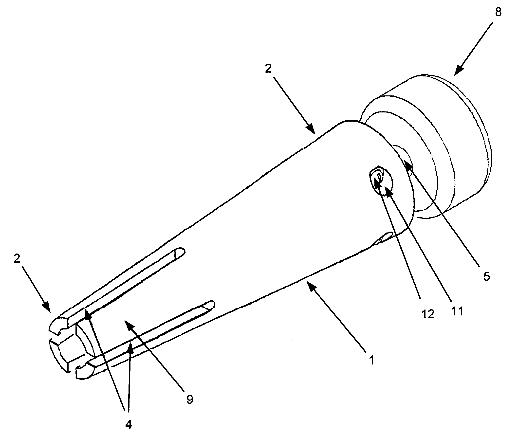
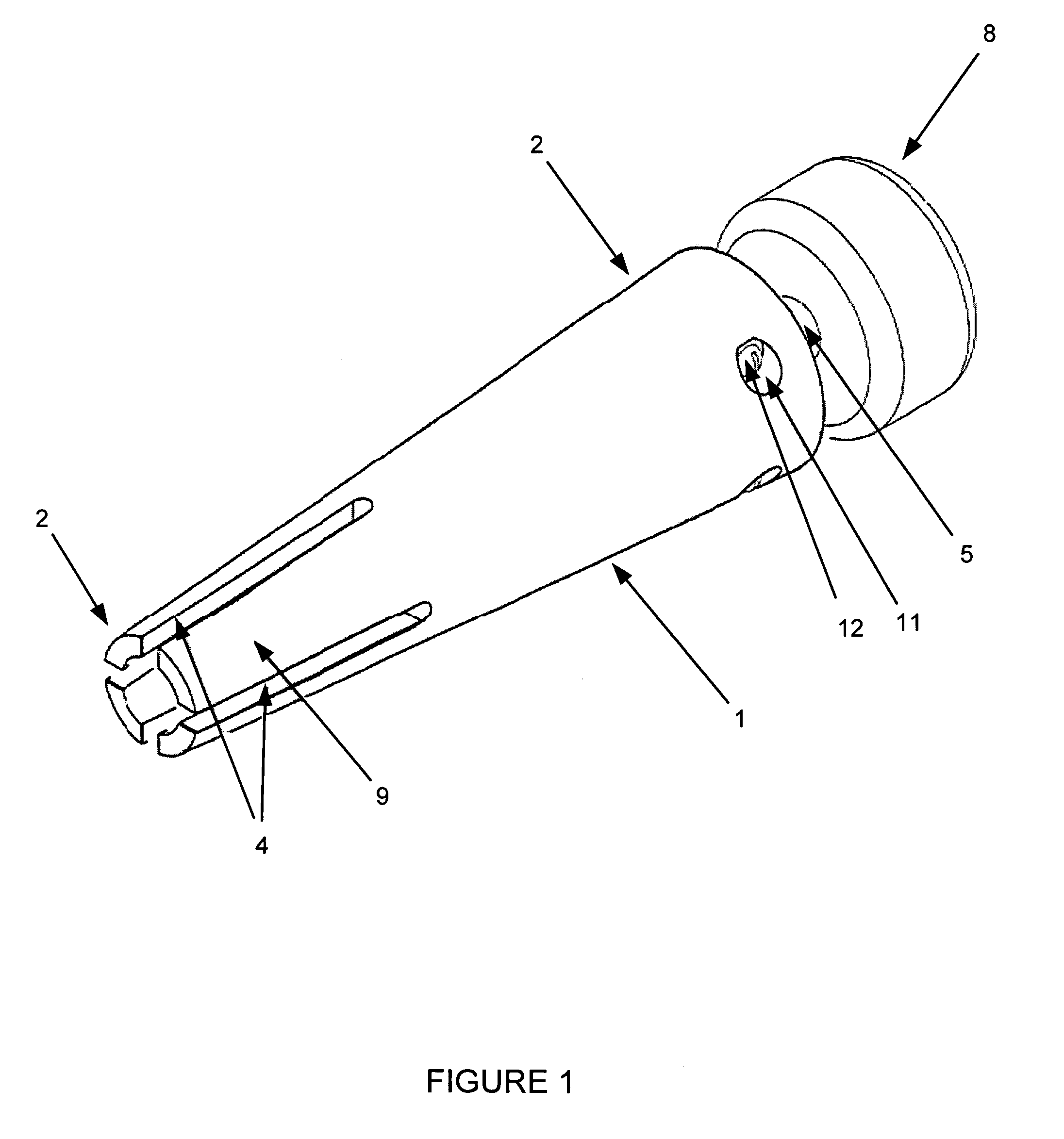
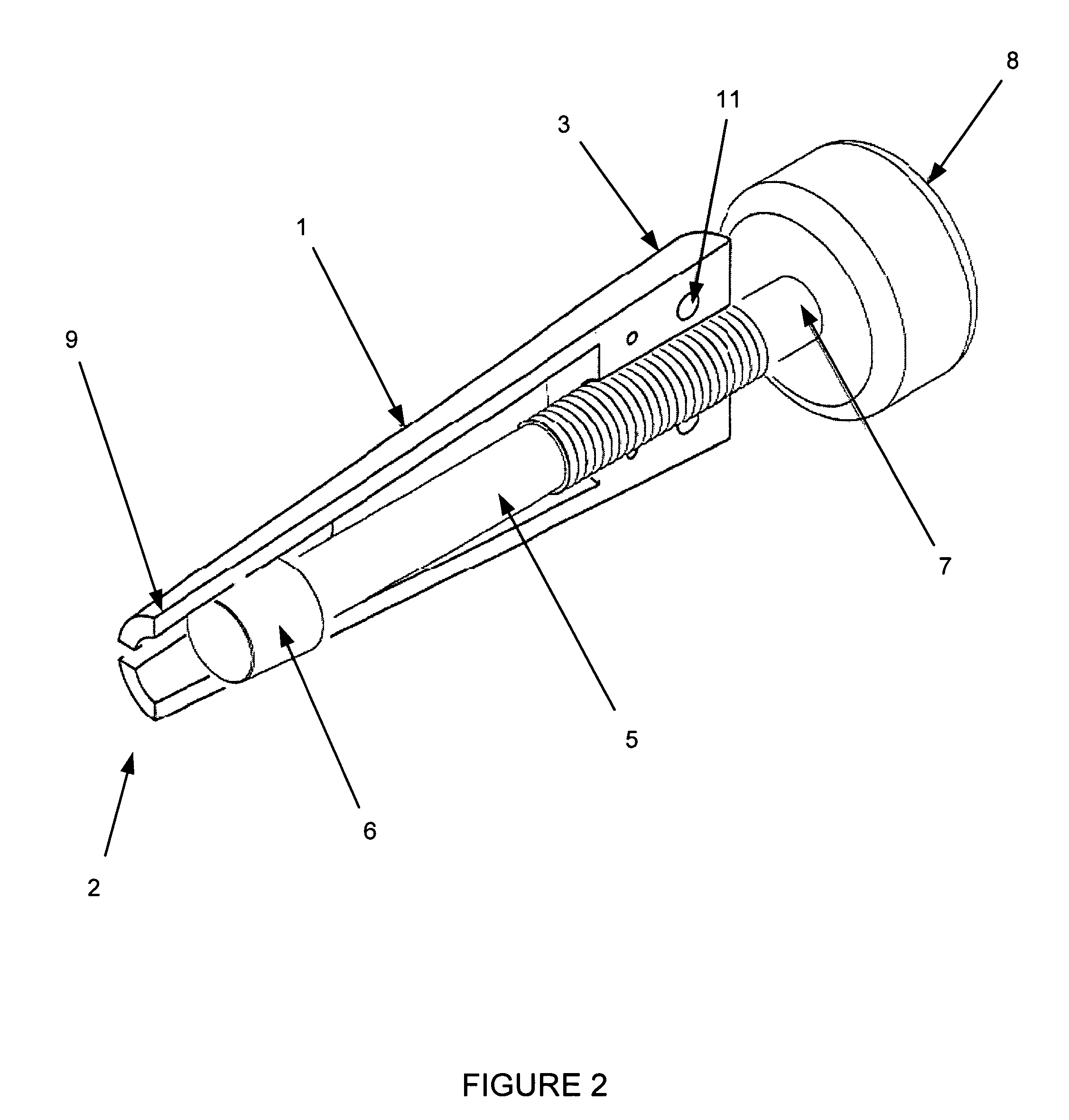
[0011]As shown in FIGS. 1, 2, and 3 a first embodiment of a device according to this invention includes a hollow elongated conical cylinder 1 with a narrower apex end 2 and an opposing wider base end 3. Two or more slits or slots 4 extend from the apex end 2 length-wise along the conical cylinder 1 for a portion of its length. As shown in FIG. 2, the diameter of the interior of the conical cylinder 1 can be variable, and the interior of the conical cylinder 1 is threaded at least partially, typically near the base end 3. A cylindrical rod 5 is located in the interior of the conical cylinder 1, with an insertion end 6 inside the conical cylinder and an opposing handle end 7 extending out through the base end 3. The cylindrical rod 5 is threaded for at least a portion of its length to match the threads on the interior of the conical cylinder 1. The insertion end 6 is moved longitudinally inside the conical cylinder 1 by screwing the rod 5 into or out of the conical cylinder 1 through ...


PUM


Abstract

A device for the extraction of the base of a broken light bulb from the socket without further breakage of any remaining glass or deformation of the bulb base member or the socket. A hollow elongated conical cylinder with a series of slots or slits at the apex of the cone is inserted into a light bulb base. A threaded cylindrical rod is screwed into threads inside the conical cylinder, causing the apex of the cone to expand and engage the inside of the light bulb base. When securely engaged, the entire device is turned to cause the light bulb base to be come disengaged from the light socket.

Description

TECHNICAL FIELD[0001]This invention relates generally to a device for removing the base of a broken light bulb from a socket.BACKGROUND OF THE INVENTION[0002]The use of a variety of devices for extracting the base of a broken light bulb from a socket is well known in the prior art. Various configurations of prior art devices are known, but the basic configuration has a substantially rigid member which forcibly engages or grips the remaining glass portion or the metal base member of the bulb. These prior art tools often result in further breakage of any remaining glass, and in deformation of the bulb base structure. Such tools also can cause deformation or damage to the socket itself.[0003]Accordingly, there is a continuing need for an improved device for the extraction of broken light bulb bases. The present invention provides an apparatus developed for the purpose of removing the base of a broken light bulb from the socket without further breakage of any remaining glass or deformat...

Claims


Application Information

Patent Timeline
Patent Type & Authority Patents(United States)
IPC IPC(8): B25B23/16B25B13/48B25B13/50H01J9/52
CPCB25B13/48H01J9/52B25B13/5083Y02W30/60Y02W30/82
Inventor SCEARCE, THOMAS R.
Owner SCEARCE THOMAS R
Why Eureka
Try Eureka