Work measurement apparatus

a technology for measuring apparatus and work, applied in bends, manufacturing tools, instruments, etc., can solve problems such as loss of a part of the electrode, damage to the electrode, etc., and achieve the effect of preventing the scoring of the electrode and the breaking of the sam

Active Publication Date: 2006-01-24
TOKYO WELD CO LTD
View PDF4 Cites 1 Cited by
  • Summary
  • Abstract
  • Description
  • Claims
  • Application Information

AI Technical Summary

Benefits of technology

[0012]An object of the present invention is to provide a work measurement apparatus in which scoring on the electrode and breaking off of the same can be prevented during the measurement process.

Problems solved by technology

In this case, since the work is being measured as it is being moved, damage to the electrodes has occurred, such as scoring damage to an electrode surface due to rubbing of the probe against the surface of the electrode, or the loss of a part of the electrode due to the probe striking against the protruding work.

Method used


Image

  • Work measurement apparatus
  • Work measurement apparatus
  • Work measurement apparatus

Examples


first embodiment

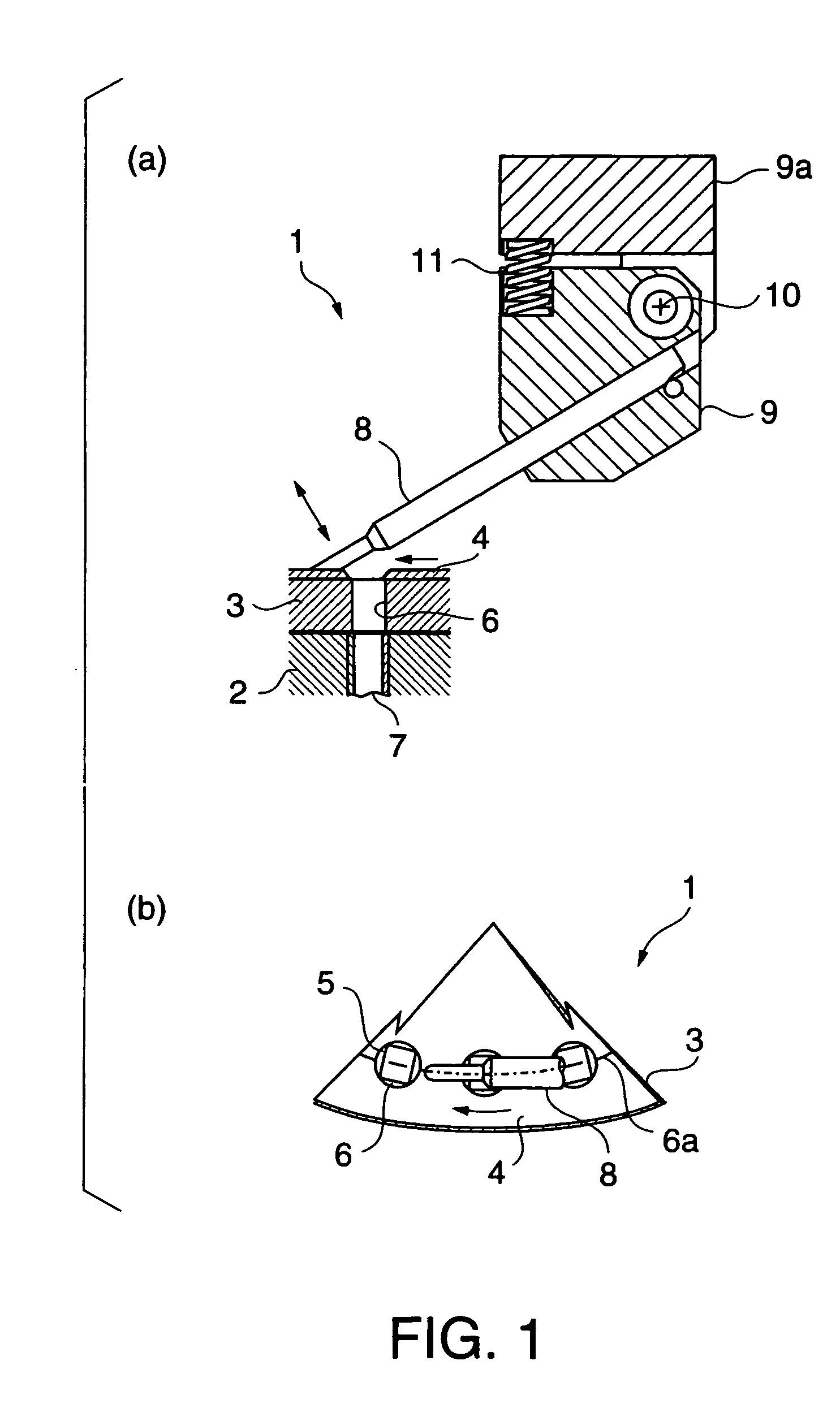
[0029]Embodiments of the invention will be explained below with reference to the drawings, beginning with FIGS. 1 and 2, which show a work measurement apparatus 1 of the present invention.

[0030]In FIGS. 1(a) (b) and 2(a)–(c), the work measurement apparatus 1 has a conveyor table 3 which rotates on a base 2.

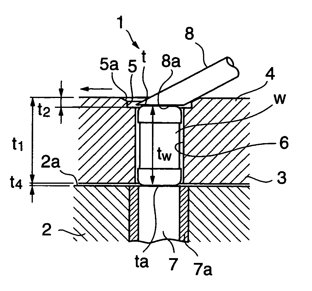
[0031]A circular guide plate 4 is disposed on the conveyor table 3. The conveyor table 3 (conveyor body) and the guide plate 4 constitute a conveyor. The conveyor 3, 4 has a plurality of work receiving openings 6 arranged concentrically at fixed intervals. The work receiving openings 6 form a work receiving opening row 6a. In this embodiment, each work receiving opening 6 penetrates through the conveyor 3, 4.

[0032]A guide entrance 5 is disposed within the guide plate 4 at the upper end part of the work receiving opening 6. The purpose of the guide entrance 5 is to lead a measurement probe 8 into the work receiving opening 6. Edges of the guide entrance 5 are formed of a sloping gu...

third embodiment

[0053]the work measurement apparatus will be explained using FIG. 4. In FIG. 4, movable measurement probes 8 are provided on both the upper and lower sides of the conveyor table 3. Fixed guide plates 4 are disposed on both sides of the conveyor table 3, and each guide plate 4 has guide entrances 5 with the sloping guide surface 5a. The movable measurement probes 8 are arranged to enter each guide entrance 5.

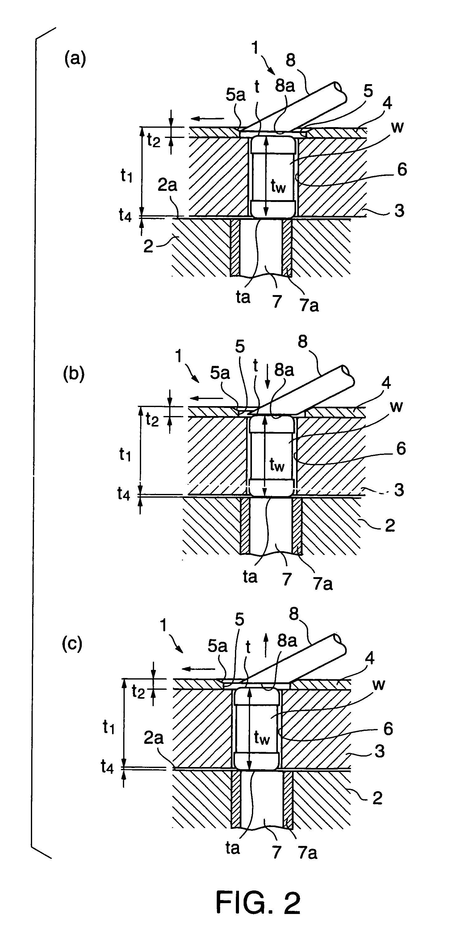
[0054]In the third embodiment, the following is true of the measurement condition: t1−t2−t3w1

[0055]t1: the thickness of the conveyor 3, 4

[0056]t2: t3: a thickness of the guide plate 4

[0057]t4: a space between the conveyor 3, 4 and the base 2

[0058]tw: a distance between the electrode end surfaces t, ta of the work W

[0059]A forth embodiment is shown in FIG. 5. In the first embodiment of FIG. 1, the guide entrance 5 is circular, but in the fourth embodiment, the guide entrance 5 may be an angular shape.

[0060]In the embodiments explained above, the conveyor consists of the base 2 an...


PUM

PropertyMeasurementUnit
electrical insulationaaaaaaaaaa
sizeaaaaaaaaaa
electrically conductiveaaaaaaaaaa

Abstract

A work measurement apparatus 1 comprises a base 2 and a conveyor table 3 which is slidably disposed on the base 2 and includes a work receiving opening 6. A guide plate 4 is fixedly disposed on the conveyor table 3. A guide entrance 5 is disposed in the guide plate 4 at the upper end of the work receiving opening 6. A measurement probe 8 is disposed on the upper side of the guide plate 4. The measurement probe 8 is urged towards the work W in the work receiving opening 6. The measurement probe 8 slides on the guide plate 4 as the conveyor table 3 is rotated. The measurement probe 8 is then directed by the guide entrance 5 to the work W in the work receiving opening 6 and makes contact with the work W. The measurement probe 8 exits from the guide entrance 5.

Description

[0001]This Nonprovisional application claims priority under 35 U.S.C. § 119(a) on Patent Application No(s). 2003-047149 filed in JAPAN on Feb. 25, 2003, the entire contents of which are hereby incorporated by reference.FIELD OF THE INVENTION[0002]The present invention relates to a work measurement apparatus for receiving a work in a receiving opening and conveying the work, and more specifically to a work measurement apparatus that can reduce the occurrence of problems caused by friction between a probe and an electrode of the work, such as scoring of the electrode or an edge of the electrode breaking off.RELATED ART[0003]In a conventional apparatus for conveying and measuring a work, the work is loaded into a conveyor in which a conveyor body is slightly thinner than the length of the work, such that the work is loaded lengthwise in a direction of an electrode. A probe makes contact with the work as the work is conveyed by the conveyor. In this case, since the work is being measure...

Claims


Application Information

Patent Timeline
Patent Type & Authority Patents(United States)
IPC IPC(8): B21B39/00B23Q5/22B23Q7/00B23B13/00B23D47/04G01R31/00G01R1/00G01R1/067G01R31/01
CPCG01R1/06705G01R31/01H02G3/0616F16L43/008F16L47/08
Inventor KOJIMA, TOMOYUKI
Owner TOKYO WELD CO LTD
Why Eureka
Try Eureka