Electrodeless discharge lamp lighting device, light bulb type electrodeless fluorescent lamp and discharge lamp lighting device

a technology of discharge lamp and lighting device, which is applied in the direction of electric variable regulation, process and machine control, instruments, etc., can solve the problems of lamp inadequacies, dimmable fluorescent lamps that have not yet developed, and difficult to implement dimmable fluorescent lamps

Inactive Publication Date: 2006-02-14
PANASONIC CORP
View PDF20 Cites 33 Cited by
  • Summary
  • Abstract
  • Description
  • Claims
  • Application Information

AI Technical Summary

Benefits of technology

[0010]A second inventive electrodeless discharge lamp operating device includes: an electrodeless discharge lamp; and a ballast circuit for applying a high-frequency voltage to the electrodeless discharge lamp, wherein the ballast circuit includes: an AC-DC converter for converting a phase-controlled AC voltage into a DC voltage; a DC-AC converter for converting the DC voltage into a high-frequency voltage; and a dimming controller for outputting an intermittent driving signal to the DC-AC converter, wherein the dimming controller includes: a circuit for generating a sawtooth wave or a triangular wave synchronized with the turn-on of the phase-controlled AC voltage; and a dimming command signal generator for generating a dimming command signal, and wherein the dimming controller is formed so as to prevent the dimming command signal from exceeding a limiter value set lower than the maximum value of the voltage variation range of the sawtooth wave or triangular wave.
[0011]In one preferred embodiment, the dimming controller has a voltage limiter, which is connected to the dimming command signal generator, for preventing the dimming command signal from exceeding the limiter value.

Problems solved by technology

On the other hand, since a fluorescent lamp emits light by discharge, it is difficult to implement a dimmable fluorescent lamp that can be practically used by merely adjusting electric power supplied thereto like an incandescent lamp.
However, the fact is that an electrodeless self-ballasted fluorescent lamp which is dimmable has not yet developed.
The present applicant has already developed an electrodeless self-ballasted fluorescent lamp that is dimmable, and succeeded in completing such a lamp; however, this lamp still has inadequacies.
For example, if dimming is carried out from full illumination state so that luminous flux is reduced, discontinuous luminous flux change occurs, thus making a user feel uncomfortable.
Even if a dimmable incandescent lamp is dimmed in such a manner, luminous flux change thereof is continuous; therefore, a user who has been using a dimmable incandescent lamp particularly feels very uncomfortable in utilizing a dimmable electrodeless self-ballasted fluorescent lamp.

Method used


Image

  • Electrodeless discharge lamp lighting device, light bulb type electrodeless fluorescent lamp and discharge lamp lighting device
  • Electrodeless discharge lamp lighting device, light bulb type electrodeless fluorescent lamp and discharge lamp lighting device
  • Electrodeless discharge lamp lighting device, light bulb type electrodeless fluorescent lamp and discharge lamp lighting device

Examples


embodiment 1

[0032](Embodiment 1)

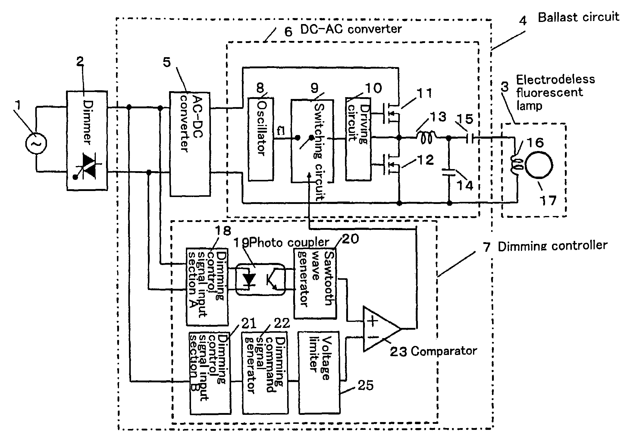
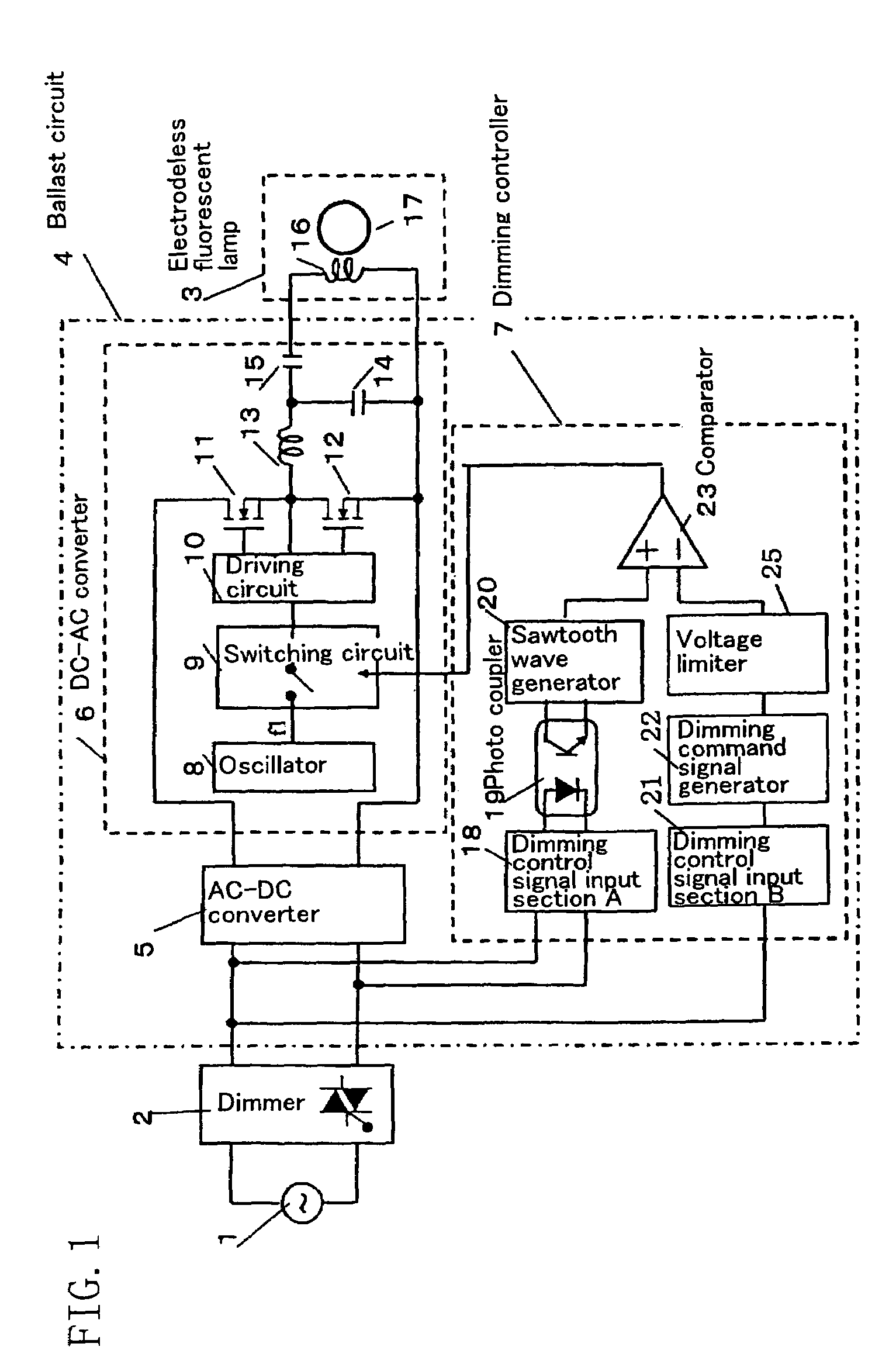
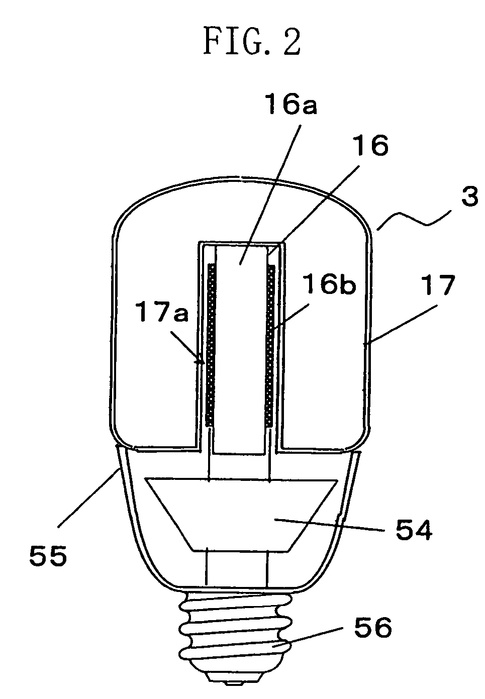
[0033]FIG. 1 schematically shows the configuration of a discharge lamp operating device (electrodeless discharge lamp operating device) according to a first embodiment of the present invention. And FIG. 2 is a cross-sectional view of the discharge lamp operating device of the present embodiment implemented as an electrodeless self-ballasted fluorescent lamp.

[0034]The electrodeless self-ballasted fluorescent lamp of the present embodiment includes: an electrodeless fluorescent lamp 3; a ballast circuit 4 (circuit board 54) for applying a high-frequency voltage to the electrodeless fluorescent lamp 3; and a lamp base 56 electrically connected to the ballast circuit 4 (circuit board 54). The circuit board 54 shown in FIG. 2 is formed with the ballast circuit 4 shown in FIG. 1. Specifically, the circuit board 54 is formed with wirings provided as shown in the ballast circuit 4, and is attached with respective circuit components.

[0035]As shown in FIG. 2, in the electr...

embodiment 2

[0074](Embodiment 2)

[0075]Hereinafter, a second embodiment of the present invention will be described with reference to FIG. 6. Although the configuration of a discharge lamp operating device of the present embodiment is similar to that described in the first embodiment, a sawtooth wave generator 20 for detecting the turn-on of a phase-controlled voltage is formed differently from the counterpart in the first embodiment, and can be formed inexpensively without using any IC in the configuration of the present embodiment.

[0076]FIG. 6 shows a circuit for detecting the turn-on of a phase-controlled voltage in the present embodiment, and in particular shows the configuration of the sawtooth wave generator 20. It should be noted that the same constituting elements as the counterparts described in the first embodiment are identified by the same reference characters, and the further description thereof will be omitted.

[0077]The sawtooth wave generator 20 shown in FIG. 6 has: a differentiati...

embodiment 3

[0082](Embodiment 3)

[0083]FIG. 7 is a circuit diagram of a discharge lamp operating device according to a third embodiment of the present invention. The third embodiment differs from the above-described first embodiment in that a discharge bulb 17′ has electrodes, and that a load resonant circuit is differently formed for the operation of a fluorescent lamp 3′ having electrodes. It should be noted that the same constituting elements as the counterparts described in the first embodiment are identified by the same reference characters, and the further description thereof will be omitted.

[0084]In the configuration of the present embodiment, as shown in FIG. 7, an LC resonant circuit including: a fluorescent lamp 3′; a resonant inductor 13; a resonant capacitor 15; and a capacitor 14 for resonance and preheat is connected between a drain terminal and a source terminal of a MOSFET 12.

[0085]In the configuration of the present embodiment, if a high voltage is generated as a resonance volta...


PUM


Abstract

An electrodeless discharge lamp operating device including an electrodeless discharge lamp 3 and a ballast circuit 4, wherein the ballast circuit 4 includes: an AC-DC converter 5 for converting a phase-controlled AC voltage into a DC voltage; a DC-AC converter 6 formed so as to intermittently drive the electrodeless discharge lamp 3 due to the existence of an operating period during which a high-frequency voltage is applied to the electrodeless discharge lamp 3 so that the electrodeless discharge lamp 3 is operated, and an extinguishing period during which the generation of the high-frequency voltage is stopped so that the electrodeless discharge lamp 3 is extinguished; and a dimming controller 7 for detecting the turn-on of the phase-controlled AC voltage, for outputting an intermittent command signal that changes the ratio between the operating period and the extinguishing period to the DC-AC converter 6, and for outputting a signal that maintains an intermittent dimmable operating state even if dimming state is in full illumination.

Description

CROSS-REFERENCE TO RELATED APPLICATIONS[0001]This application is a National Stage of International Application No. PCT / JP03 / 07235, filed Jun. 6, 2003. This application claims the benefit of 2002-167613, filed Jun. 7, 2002. The disclosure of the above applications are incorporated herein by reference.TECHNICAL FIELD[0002]The present invention relates to discharge lamp operating devices and electrodeless discharge lamp operating devices. In particular, the present invention relates to electrodeless self-ballasted fluorescent lamps in which electrodeless fluorescent lamps can be dimmed.BACKGROUND ART[0003]A fluorescent lamp has been widely used from global environmental protection and economic standpoints because it has a higher degree of efficiency and a longer life as compared with an incandescent lamp. In recent years, as an economical light source, an electrodeless self-ballasted fluorescent lamp having no electrode has been attracting much attention since its life is several times...

Claims


Application Information

Patent Timeline
Patent Type & Authority Patents(United States)
IPC IPC(8): H05B41/16H05B41/24H05B41/28H05B41/285H05B41/392
CPCH05B41/24H05B41/2806H05B41/2853H05B41/3921H05B41/3927H05B41/3924Y10S315/04Y02B20/186Y02B20/22Y02B20/00
Inventor TAKAHASHI, KENICHIROKOMINAMI, SATOSHIMIYAZAKI, KOUJIKURACHI, TOSHIAKIMATSUBAYASHI, YOKOTAKEDA, MAMORU
Owner PANASONIC CORP
Why Eureka
Try Eureka