LED illumination apparatus and card-type LED illumination source

a technology of led illumination and led bare chips, which is applied in the direction of solid-state devices, lighting support devices, coupling device connections, etc., can solve the problems of unintentional decrease of the luminous efficacy significant effect of bare chip temperature on the life of the led bare chip, and none of the conventional led illumination sources has ever succeeded in coping with all of those problems satisfactorily

Inactive Publication Date: 2005-09-27
EVERLIGHT ELECTRONICS
View PDF8 Cites 388 Cited by
  • Summary
  • Abstract
  • Description
  • Claims
  • Application Information

AI Technical Summary

Benefits of technology

[0032]In another preferred embodiment, the illumination apparatus includes: a receiving portion, on / from which the card-type LED illumination source is fixable and removable; and stopper means for keeping the card-type LED illumination source from dropping from the receiving portion. The stopper means operates in such a manner as to allow a human user to remove the card-type LED illumination source from the receiving portion with his or her fingers.

Problems solved by technology

However, to make such an LED illumination apparatus a commercially viable product, the following problems must be solved.
Generally speaking, the bare chip temperature has significant effects on the life of the LED bare chip.
What is worse, when the bare chip temperature rises with the increase in the quantity of heat generated, the luminous efficacy of the LED bare chip 22 decreases unintentionally.
However, none of those conventional LED illumination sources has ever succeeded in coping with all of those problems satisfactorily.
Firstly, if the LEDs are kept ON continuously for a long time, the center portion of the substrate, having the huge number of LEDs integrated thereon, gets more and more heated.
As a result, the difference in temperature between the center and peripheral portions of the LED substrate escalates with time.
However, when LEDs are used to make an illumination apparatus, all of those LEDs must be kept ON for a long time, thus causing a non-negligible heat generation problem.
However, a resin material normally has a low thermal conductivity, and easily stores the heat generated.
For that reason, such a resin material cannot be used so effectively in an illumination apparatus that should always be kept ON at the maximum output power.
Even so, the heat-dissipating and uniform thermal distributing performance is also limited by the thermal conductivity of the substrate material.
Furthermore, when the above-described configuration is adopted, the substrate itself needs to be thick enough and the substrate to mount the LED bare chips 22 thereon cannot have a reduced thickness.
Accordingly, when kept energized or ON for a long time with a great amount of current supplied as in an illumination apparatus, the LED bare chips, mounted around the center of the substrate, in particular, will have noticeably increased temperatures, thus creating a big temperature difference between the center and peripheral portions of the substrate.
Consequently, the properties of the substrate material with the high thermal conductivity cannot be made full use of, and the heat dissipation problem is still insoluble.
Furthermore, unless the recesses to be provided on the surface of the substrate have relatively large sizes, a sufficient space cannot be allowed to mount the LED bare chips 22 thereon and conductive line the LED bare chips 22 by the wire bonding technique.
Also, it is currently difficult to mount the LED bare chips 22 inside the recesses considering the capillary and collet sizes of bonders of various types.

Method used


Image

  • LED illumination apparatus and card-type LED illumination source
  • LED illumination apparatus and card-type LED illumination source
  • LED illumination apparatus and card-type LED illumination source

Examples


embodiment 1

[0097]FIG. 3(a) is a perspective view illustrating a portion of an LED illumination apparatus according to the present invention and shows a heat sink 19 in which multiple insertable / removable card-type LED illumination sources 10 are fitted.

[0098]Each of the card-type LED illumination sources 10 is inserted to a predetermined position through a slot, which is provided on a side surface of the heat sink 19. The heat sink 19 thermally contacts with the back surface of the card-type LED illumination source 10 inserted, thereby dissipating the heat away from the back surface of the substrate of the card-type LED illumination source 10.

[0099]When inserted in the heat sink 19, the card-type LED illumination sources 10 are electrically connected to a connector (not shown), which is provided inside the heat sink 19. The card-type LED illumination sources 10 are further connected electrically to a lighting drive circuit (not shown) by way of the connector. As used herein, the “connector” re...

embodiment 2

[0116]Next, specific preferred embodiments of a card-type LED illumination source according to the present invention will be described.

[0117]FIGS. 4(a) and 4(b) illustrate a configuration for a card-type LED illumination source according to a second specific embodiment. The card-type LED illumination source of this embodiment is preferably for use in the illumination apparatus shown in FIG. 3(a) or 3(b).

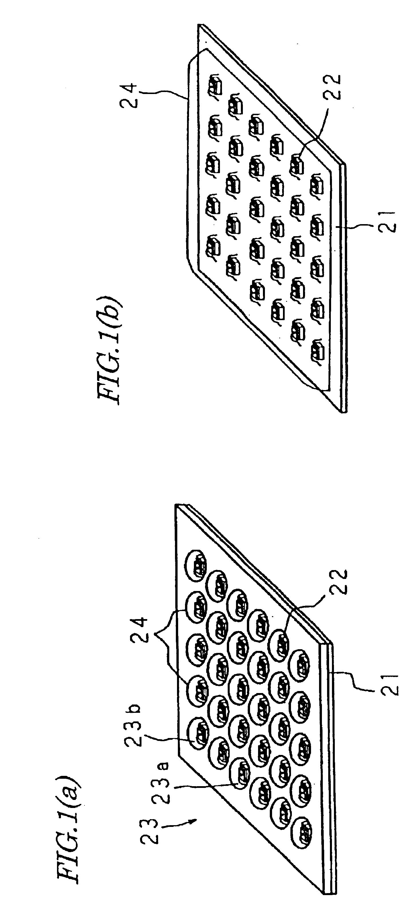
[0118]In the card-type LED illumination source of this embodiment, multiple LED bare chips 2 are mounted on one surface of a heat-dissipating substrate 1 as shown in FIG. 4(a). In the example illustrated in FIG. 4(a), the LED bare chips 2 are arranged in matrix, or in columns and rows. However, the present invention is in no way limited to this specific preferred embodiment. Thus, the LED bare chips 2 may be arranged in any other arbitrary pattern.

[0119]The heat-dissipating substrate 1 with the LED bare chips 2 mounted thereon is further combined with the optical reflector 3 shown in...

embodiment 3

[0164]Next, another specific embodiment of a card-type LED illumination source according to the present invention will be described.

[0165]First, a card-type LED illumination source according to this embodiment will be described with reference to FIG. 12.

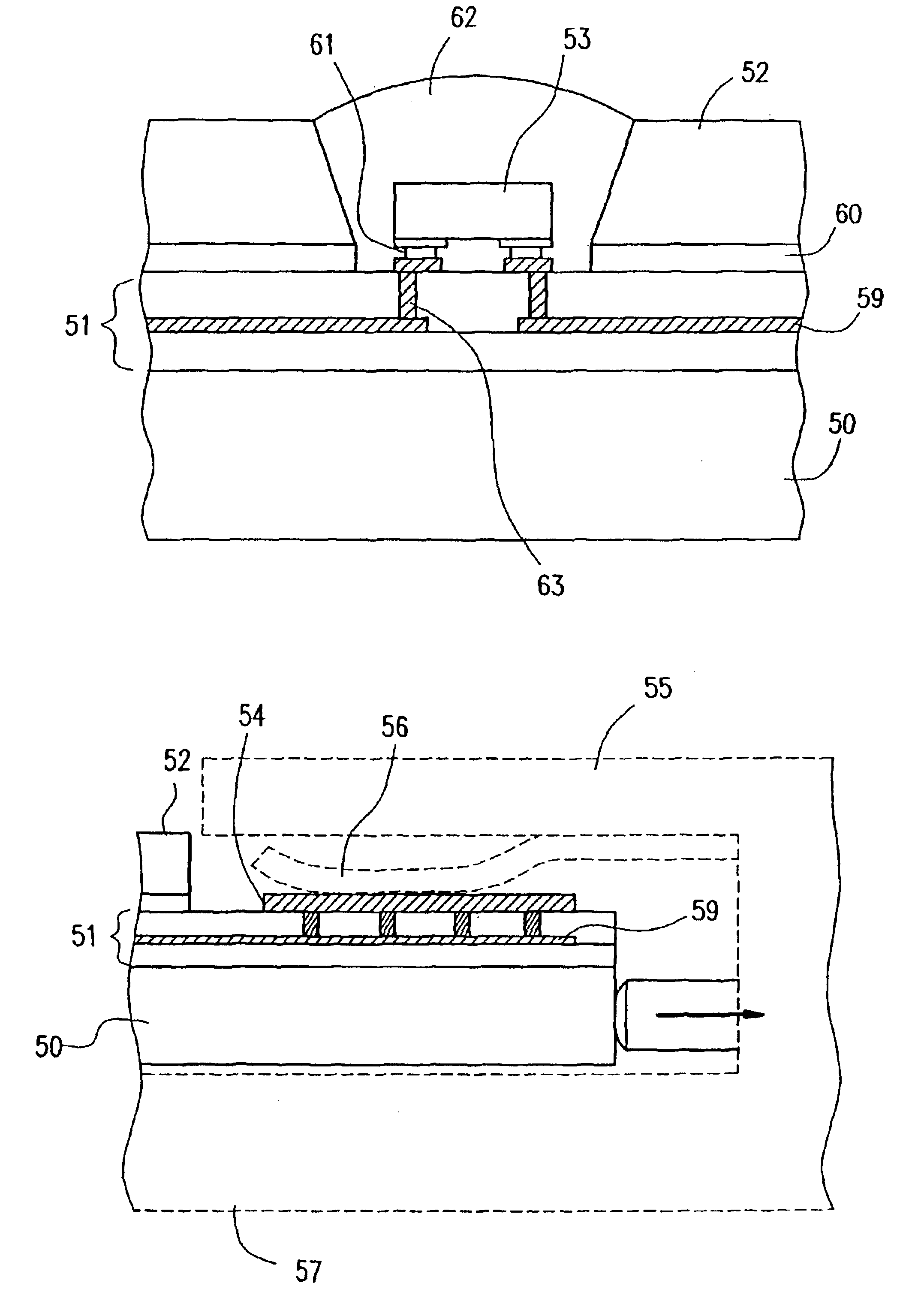
[0166]As shown in FIG. 12, the card-type LED illumination source of this embodiment includes a metal plate 50, a multilayer circuit board 51, and a metallic optical reflector 52. The metal plate 50 and the multilayer circuit board 51 together define one “card-type LED illumination source”.

[0167]The metal plate 50 is the base metal of a heat-dissipating substrate. The metal plate 50 and the optical reflector 52 may be made of aluminum, copper, stainless steel, iron, or an alloy thereof. The materials of the metal plate 50 and optical reflector 52 may be different from each other. Considering the thermal conductivity, copper, aluminum, iron and stainless steel are preferred in this order. On the other hand, in view of the thermal expan...


PUM


Abstract

An LED illumination apparatus according to the present invention includes at least one connector and a lighting drive circuit. The connector is connected to an insertable and removable card-type LED illumination source, which includes multiple LEDs that have been mounted on one surface of a substrate. The lighting drive circuit is electrically connected to the card-type LED illumination source by way of the connector. The card-type LED illumination source preferably includes a metal base substrate and the multiple LEDs that have been mounted on one surface of the metal base substrate. The back surface of the metal base substrate, including no LEDs thereon, thermally contacts with a portion of the illumination apparatus. A feeder terminal to be electrically connected to the connector is provided on the surface of the metal base substrate on which the LEDs are provided.

Description

CROSS-REFERENCE TO RELATED APPLICATION[0001]This application is a Continuation of International Application Ser. No. PCT / JP02 / 08151, filed Aug. 8, 2002, the disclosure of which is incorporated herein by reference.TECHNICAL FIELD[0002]The present invention relates to an LED (Light Emitting Diode) illumination apparatus and a card-type LED illumination source. More specifically, the present invention relates to an LED illumination apparatus that uses a card-type LED illumination source on which multiple LEDs are mounted, and also relates to such a card-type LED illumination source that can be used effectively in that LED illumination apparatus.BACKGROUND ART[0003]Incandescent lamps, fluorescent lamps, high-pressure discharge lamps and other types of lamps have been used as luminaries or light sources for billboards. Recently, an LED illumination source has been researched and developed as a new type of illumination source that could potentially replace these conventional light sources...

Claims


Application Information

Patent Timeline
Patent Type & Authority Patents(United States)
IPC IPC(8): H01L25/075H01R33/05H01R33/22F21K99/00F21V9/00H01L33/64
CPCF21K9/13F21V19/003H01L24/97F21S6/003F21V19/045H05B33/0803H05B33/0821H05B33/0842H05B33/0863H01R12/714F21L4/00F21L4/005H01L2924/07811H01L2224/49107H01L2224/48227H01L2224/48091H01L2224/16225H01L2924/12041H01L2224/45144H01L2924/01019F21L4/027F21S2/00F21S6/00F21V7/0083F21V29/004F21Y2101/02F21Y2103/022F21Y2105/001H01L25/0753H01L33/64H01L2224/16H01L2224/48465H01L2924/01004H01L2924/01078H01L2924/01079H01L2924/09701H01R33/225H05K1/112H05K1/117H01L2924/00H01L2924/00014H01L2924/15787H01L2924/181H01L2224/05573H01L2224/05568F21Y2105/00F21Y2105/10F21K9/23F21Y2115/10F21Y2115/20F21Y2103/33F21Y2115/15H01L33/20H05K1/05H05K2201/10106F21V19/04F21V29/70H05B45/40H05B45/20H05B45/00H01L2224/06102H01L2224/1703H05B45/37H05B45/3578H05B45/345H05B45/3574H01L2224/05599H01L2924/00012
Inventor SHIMIZU, MASANORIYANO, TADASHISETOMOTO, TATSUMIMATSUI, NOBUYUKITAMURA, TETSUSHI
Owner EVERLIGHT ELECTRONICS
Why Eureka
Try Eureka