Method of calibrating a daylight sensor

a technology of daylight sensor and calibration method, which is applied in the field of daylight sensor, can solve the problems of tedious calibration procedures of most prior art daylight sensor and many steps

Active Publication Date: 2013-04-02
LUTRON TECH CO LLC
View PDF28 Cites 389 Cited by
  • Summary
  • Abstract
  • Description
  • Claims
  • Application Information

AI Technical Summary

Problems solved by technology

However, the calibration procedures of most prior art daylight sensors are tedious and require many steps that involve human interaction with the daylight sensor.

Method used


Image

  • Method of calibrating a daylight sensor
  • Method of calibrating a daylight sensor
  • Method of calibrating a daylight sensor

Examples


first embodiment

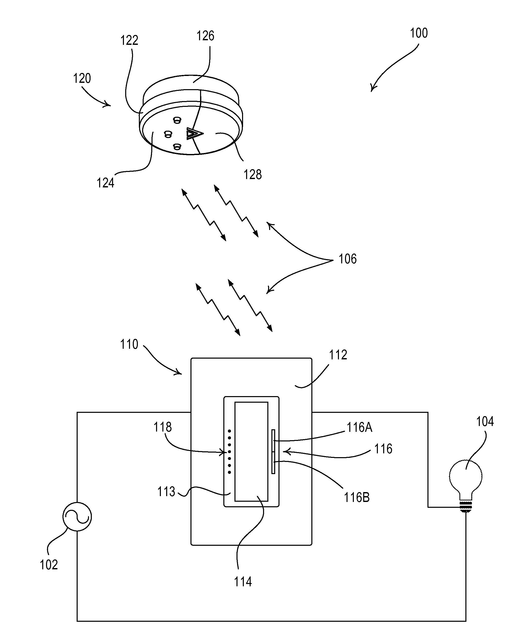
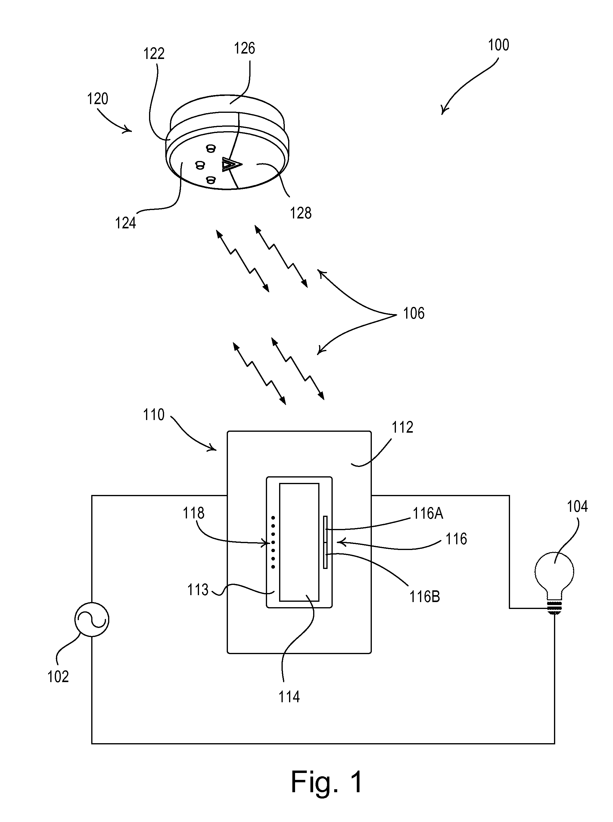
[0045]FIG. 1 is a simple diagram of a radio-frequency (RF) lighting control system 100 comprising a load control device (e.g., a dimmer switch 110) and a daylight sensor 120 according to the present invention. The dimmer switch 110 is adapted to be coupled in series electrical connection between an alternating-current (AC) power source 102 and a lighting load 104 for controlling the amount of power delivered to the lighting load. The dimmer switch 110 may be wall-mounted in a standard electrical wallbox, but could alternatively be implemented as a table-top load control device. As shown in FIG. 1, the dimmer switch 110 comprises a faceplate 112 and a bezel 113 received in an opening of the faceplate. The dimmer switch 110 further comprises a control actuator 114 (i.e., a button) and an intensity adjustment actuator 116. Actuations of the toggle actuator 114 toggle, i.e., turn off and on, the lighting load 104. Actuations of an upper portion 116A or a lower portion 116B of the intens...

third embodiment

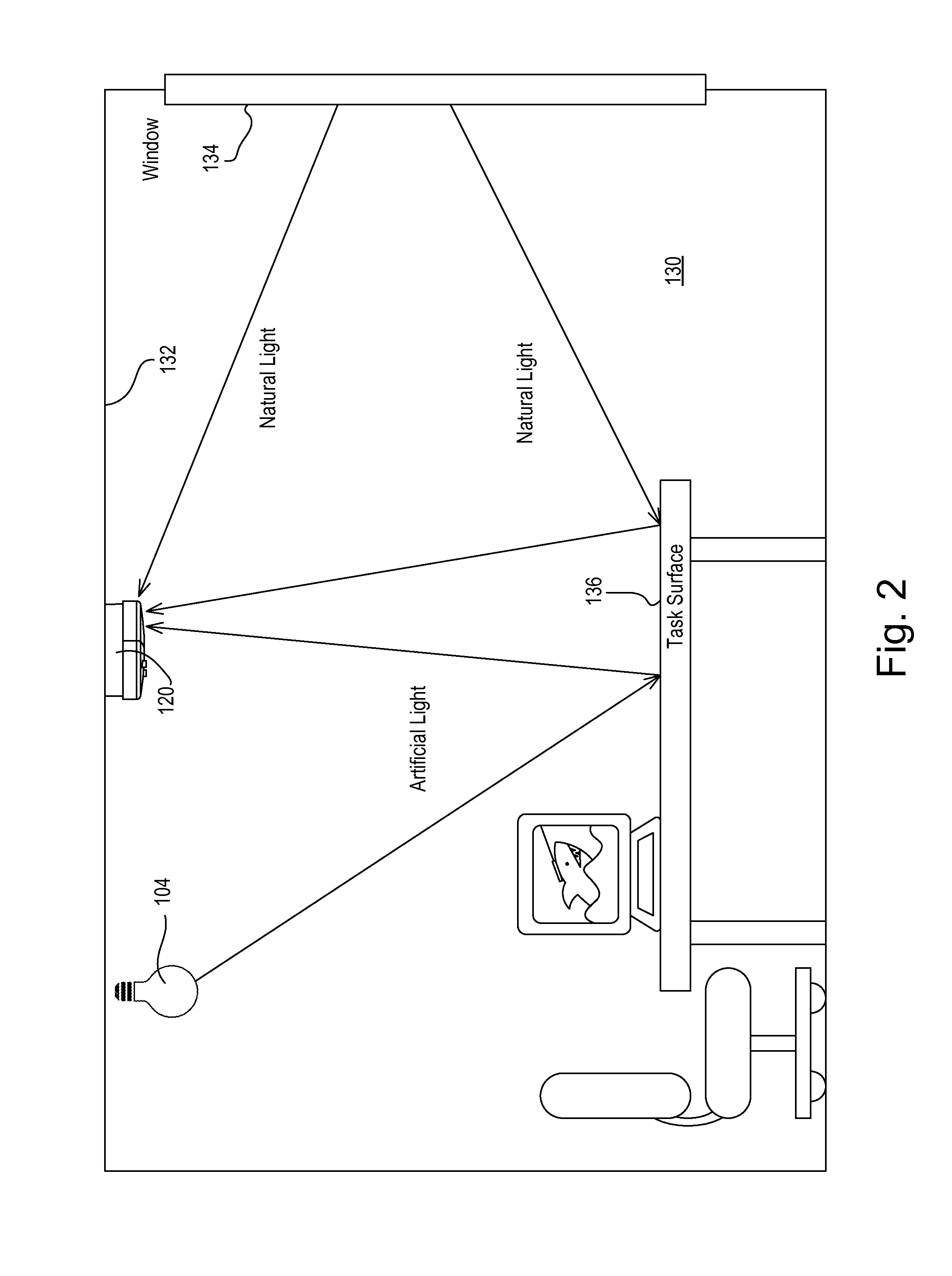
[0093]FIG. 15B is a simplified high-level flowchart of a semi-automatic daylight sensor calibration procedure 1170 completed by a user to enable a first daylight sensor to determine the appropriate gain M according to the present invention. The user first mounts the first daylight sensor to the ceiling 132 at step 1172, and then places a second daylight sensor on the task surface 136 at step 1174. The user then adjusts the present light intensity LPRES of the lighting load 104 to achieve the target total light intensity LTRGT-TASK on the task surface 136 at step 1176 using, for example, the raise and lower buttons 152, 154 of the second daylight sensor. After the user actuates the calibration button 150 on the second daylight sensor once at step 1178, the first daylight sensor measures the total light intensity LT-SNSR at the first daylight sensor at step 1180, the second daylight sensor measures the total light intensity LT-SNSR at the second daylight sensor at step 1182, and the s...

fourth embodiment

[0096]FIG. 16 is a simplified flowchart of a startup procedure 1200 executed by the controller 230 of the daylight sensor 120 each time the controller is powered up at step 1210 according to the present invention. If there is not operational data (i.e., the daylight gain GD and an electric light gain GE) stored in the memory 246 at step 1212, the controller 230 sets the daylight gain GD equal to a default daylight gain value GD-DEF (e.g., approximately 1.5) and the electric light gain GE equal to a default electric light gain value GE-DEF (e.g., a large number, such as 256) at step 1214. The default daylight gain value GD-DEF is an assumption of a daylight gain of a typical room in which the daylight sensor may be installed. In addition, the controller 230 of the daylight sensor 120 sets total light intensity LT-TASK on the task surface 136 and a maximum light intensity LEM-TASK on the task surface 136 from only the lighting load 104 equal to the total task surface light intensity L...


PUM


Abstract

A wireless lighting control system comprises a daylight sensor for measuring a light intensity in a space and a dimmer switch for controlling the amount of power delivered to a lighting load in response to the daylight sensor. For example, the daylight sensor may be able to transmit radio-frequency (RF) signals to the dimmer switch. The system provides methods of calibrating the daylight sensor that allow for automatically measuring and / or calculating one or more operational characteristics of the daylight sensor. One method of calibrating the daylight sensor comprises a “single-button-press” calibration procedure during which a user is only required to actuate a calibration button of the daylight sensor once. In addition, the daylight sensor is operable to automatically measure the total light intensity in the space at night to determine the light intensity of only the electrical light generated by the lighting load.

Description

CROSS-REFERENCE TO RELATED APPLICATIONS[0001]This application is a non-provisional application of commonly-assigned U.S. Provisional Application Ser. No. 61 / 164,098, filed Mar. 27, 2009, entitled METHOD OF CALIBRATING A DAYLIGHT SENSOR, and U.S. Provisional Application Ser. No. 61 / 174,322, filed Apr. 30, 2009, entitled WIRELESS BATTERY-POWERED DAYLIGHT SENSOR, the entire disclosures of which are hereby incorporated by reference.BACKGROUND OF THE INVENTION[0002]1. Field of the Invention[0003]The present invention relates to daylight sensors for measuring the ambient light level (i.e., the total light intensity) in a space, and more particularly, to method of calibrating a daylight sensor of a lighting control system having a lighting control device, such as a dimmer switch.[0004]2. Description of the Related Art[0005]Many rooms in both residential and commercial buildings are illuminated by both artificial light (i.e., electric light) from a lighting load, such as an incandescent lam...

Claims


Application Information

Patent Timeline
Patent Type & Authority Patents(United States)
IPC IPC(8): H05B37/02
CPCG01J1/02G01J1/0219G01J1/0233G01J1/16G01J1/1626G01J1/32G01J1/4228H05B37/0218Y02B20/46H05B47/11Y02B20/40
Inventor STEINER, JAMES P.SLOAN, GREG EDWARD
Owner LUTRON TECH CO LLC
Why Eureka
Try Eureka