
Lighting device and method of making

a technology of light source and light source, which is applied in the direction of lighting and heating apparatus, discharge tube luminescnet screens, light source combinations, etc., can solve the problems of low efficacy, low to medium cri ra, and methods with good efficacy but only medium cri or very good cri, and achieve high cri

Active Publication Date: 2009-07-23
IDEAL IND LIGHTING LLC
View PDF99 Cites 402 Cited by
  • Summary
  • Abstract
  • Description
  • Claims
  • Application Information

AI Technical Summary

Benefits of technology

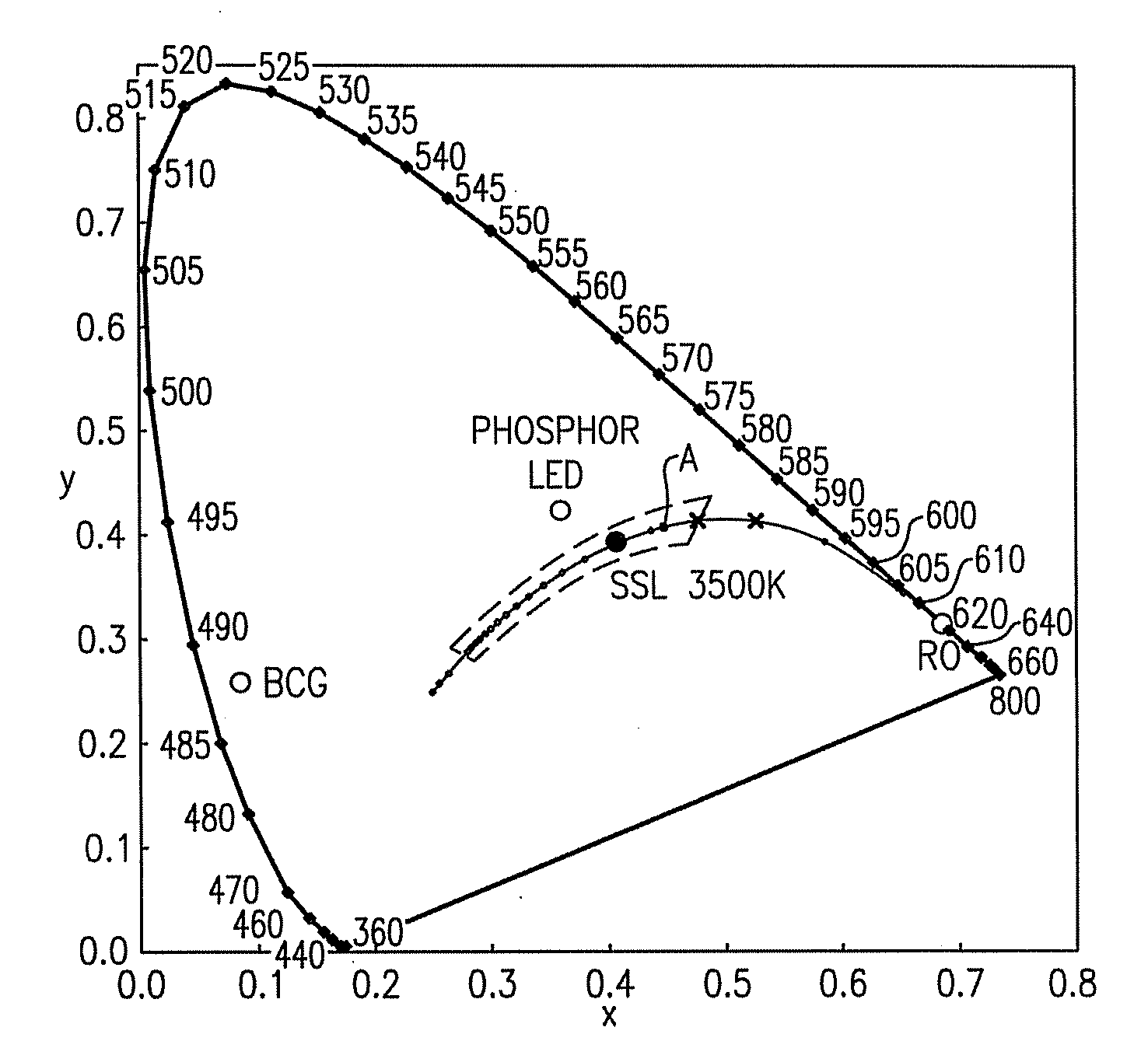
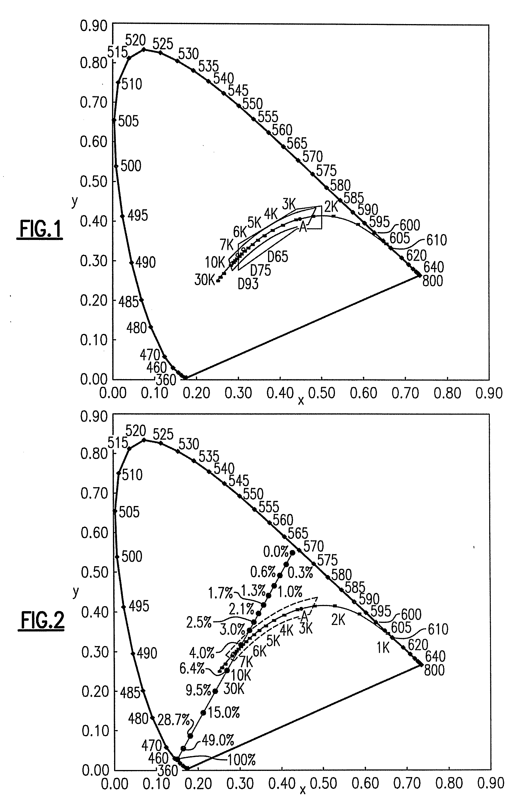
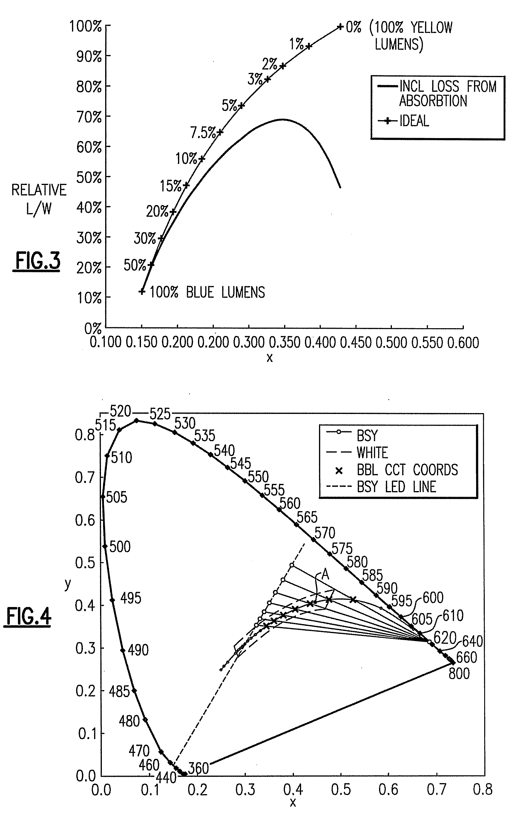
[0029]The present inventive subject matter provides lighting devices which comprise at least one or more non-white light sources (e.g., non-saturated phosphor LEDs which emit off-white or low to medium purity color), a second light source emitting light in the red to orange part of the color spectrum and a third light source emitting light in the blue to green spectrum. In some embodiments, the mixed light from the three (or more)

Problems solved by technology

However, all these methods generally provide low to medium CRI Ra.
These methods have good efficacy but only medium CRI or very good CRI and low efficacy.
The efficacy and CRI tradeoff in LEDs is also an issue in the lighting industry with regard to fluorescent illumination.
Illumination with a CRI Ra of less than 50 is very poor and only used in applications where there is no alternative for economic issues.
Light made from combinations of standard “pure colors,” red, green and blue, exhibit poor efficacy due primarily to the poor quantum efficiency of green LEDs.
Red AlInGaP LEDs have very high internal quantum efficiency, but due to the large refractive index mismatch between AlInGaP and suitable encapsulant materials, a lot of light is lost due to total internal reflection (TIR).
While the arrangement disclosed in Vitta '056 allows the CCT to be changed, the CRI and the usefulness of the device reduces significantly at lower color temperatures, making this arrangement generally undesirable for indoor general illumination.

Method used


Image

  • Lighting device and method of making
  • Lighting device and method of making
  • Lighting device and method of making

Examples


examples

[0183]Light emitting diodes have been demonstrated to be able to produce white light with efficacy >150 L / W and are anticipated to be the predominant lighting devices within the next decade. LED based luminaires are already commercially available with efficacies up to 60 L / W. Many systems are based primarily on LEDs which combine blue+YAG:Ce or BOSE, or RGB InGaN / AlInGaP LEDs or UV LED excited RGB phosphors. These methods have good efficacy but only medium CRI. They have not been able to demonstrate both high CRI and high efficacy especially with color temperatures between 2700K and 4000K. The general approach described in U.S. Pat. No. 7,213,940 was utilized to produce white light and demonstrate a warm-white luminaire with a wall plug efficacy of 85 lumens per watt, a CRI Ra of 92 at a CCT of 2865K. By combining high efficiency AlInGaP Red LEDs and wide spectrum yellowish phosphor LEDs, high-efficacy high-CRI warm-white illumination was produced.

[0184]A YAG:Ce phosphor was combine...


PUM


Abstract

A lighting device comprising at least one non-white light source, at least a first supplemental light emitter and at least a second supplemental light emitter. The non-white light source(s) is outside an area from 0.01 u′v′ above to below the blackbody locus, and within an area defined by curves between saturated light of wavelength 430-480 nm and 560-580 nm and line segments between saturated light of wavelength 430-580 nm and 480-560 nm. The first supplemental light emitter(s) have dominant emission wavelength of 465-540 nm. The second supplemental light emitter(s) have dominant emission wavelength of 600-640 nm.

Description

CROSS-REFERENCE TO RELATED APPLICATIONS[0001]This application claims the benefit of U.S. Provisional Patent Application No. 60 / 978,880, filed Oct. 10, 2007, the entirety of which is incorporated herein by reference.[0002]This application claims the benefit of U.S. Provisional Patent Application No. 61 / 037,365, filed Mar. 18, 2008, the entirety of which is incorporated herein by reference.FIELD OF THE INVENTIVE SUBJECT MATTER[0003]The present inventive subject matter relates to lighting devices and methods of making them. In some embodiments, the present inventive subject matter relates to a lighting device which includes one or more non-white light sources and at least two supplemental light emitters which improve the CRI Ra of the light emitted from the lighting device. In addition, some embodiments of the present inventive subject matter provide lighting devices which respectively emit light of high CRI Ra in a wide range of color temperatures.BACKGROUND[0004]Color reproduction is...

Claims


Application Information

Patent Timeline
IPC IPC(8): H01J61/94
CPCF21Y2101/02H05B33/086F21V23/0457F21K9/137F21Y2113/005H01L2224/48091H01L2224/48247F21K9/233F21Y2115/10F21Y2113/13H01L2924/13091H05B45/20H05B45/28H01L2924/00014H01L2924/00
Inventor VAN DE VEN, ANTONY PAULNEGLEY, GERALD H.
Owner IDEAL IND LIGHTING LLC
Learn More