Tube rack accommodating a range of tube diameters

a tube rack and tube diameter technology, applied in the field of specimen sampling equipment and liquid handling equipment, can solve the problems of metal spring arms, limited tube diameter range that the chamber can accommodate, and expensive construction of racks

Inactive Publication Date: 2006-02-21
BIO RAD LAB INC
View PDF36 Cites 48 Cited by
  • Summary
  • Abstract
  • Description
  • Claims
  • Application Information

AI Technical Summary

Problems solved by technology

Even with four spring arms distributed around the circumference of the chamber, the tube orientation is only secured at one location along the height of the tube, and the range of tube diameters that the chamber can accommodate is limited.
The rack also suffers from costly construction since the spring arms have a V-shaped cross section and are angled at each end toward the vertical.
In the assembled rack, the metal spring arms are fitted into the body but susceptible to slippage and potential disengagement.

Method used


Image

  • Tube rack accommodating a range of tube diameters
  • Tube rack accommodating a range of tube diameters
  • Tube rack accommodating a range of tube diameters

Examples


Embodiment Construction

[0010]While this invention is susceptible to a variety of configurations, arrangements and embodiments, the following discussion will focus on a specific example of a tube rack used for sample tubes. The structural and functional aspects of the rack in this example will serve to provide an understanding of the invention as a whole.

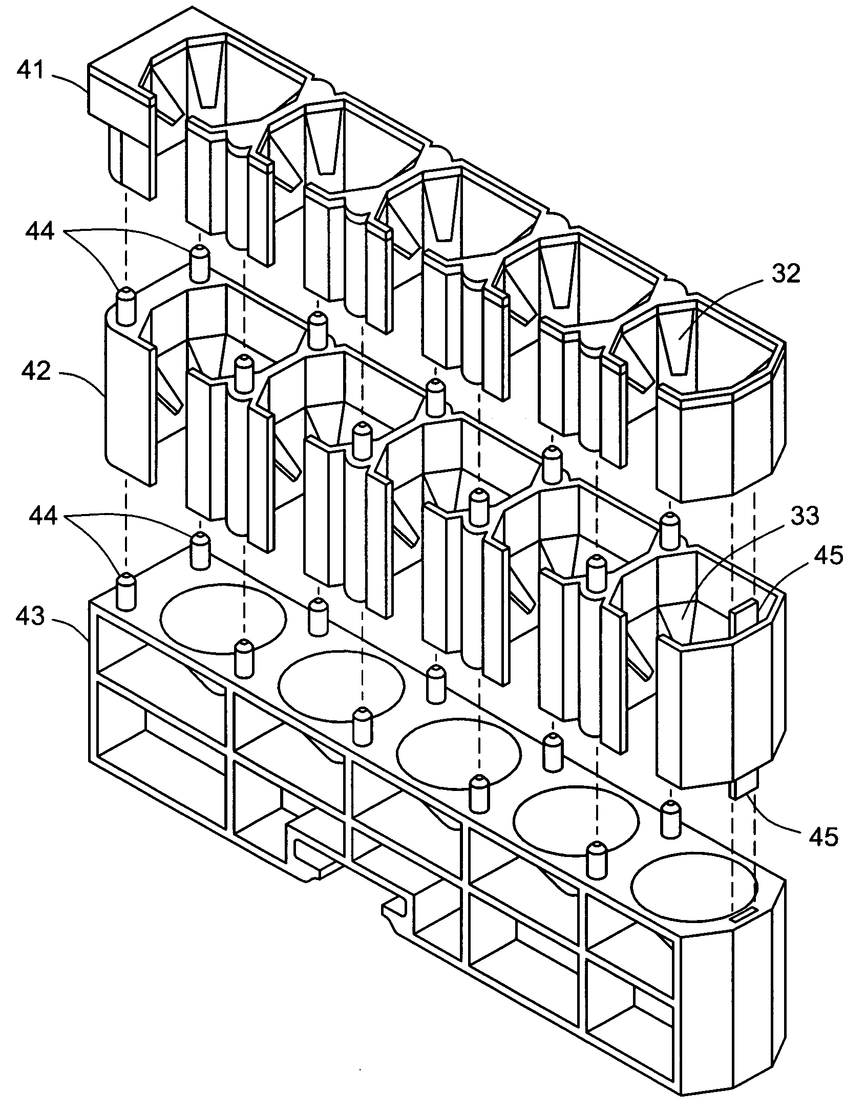
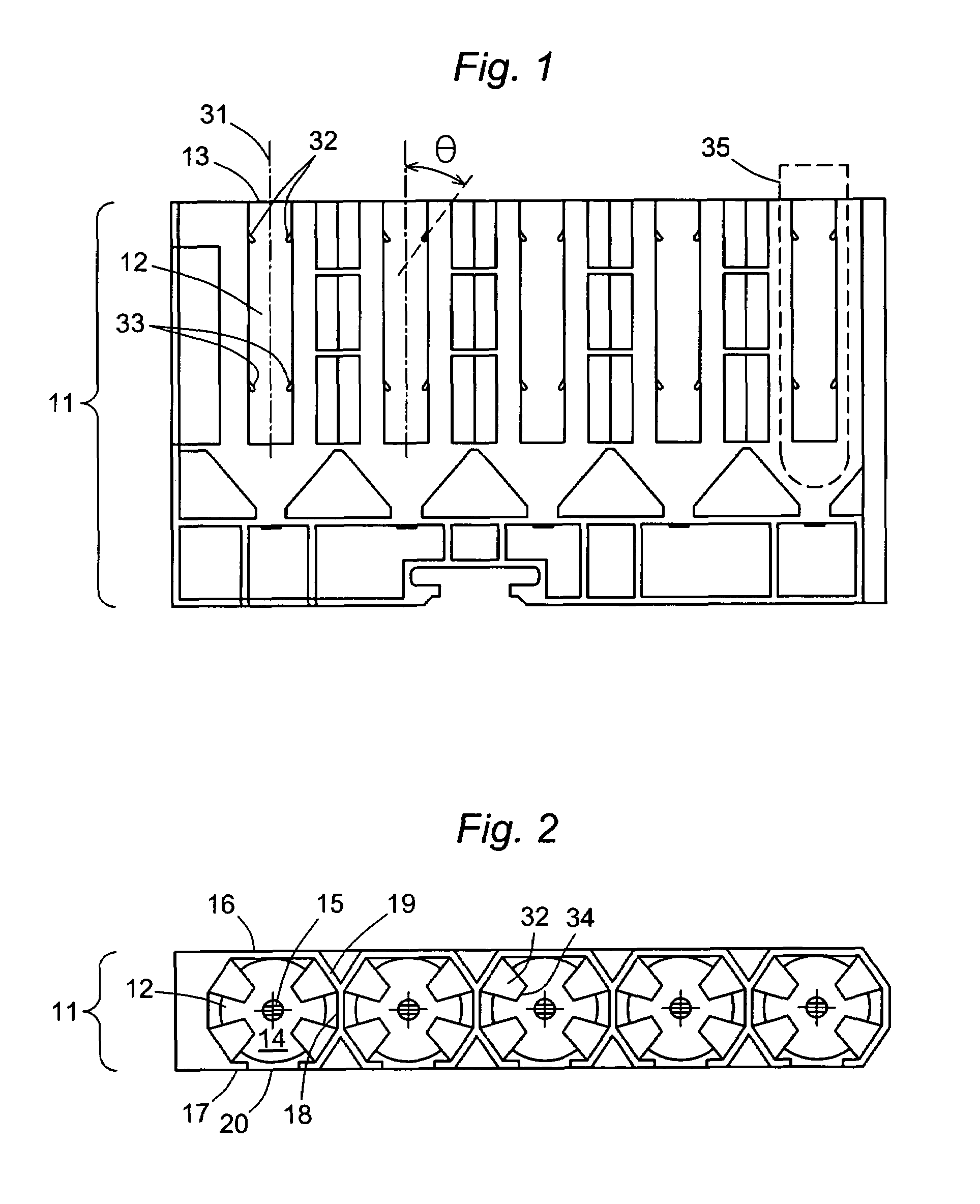
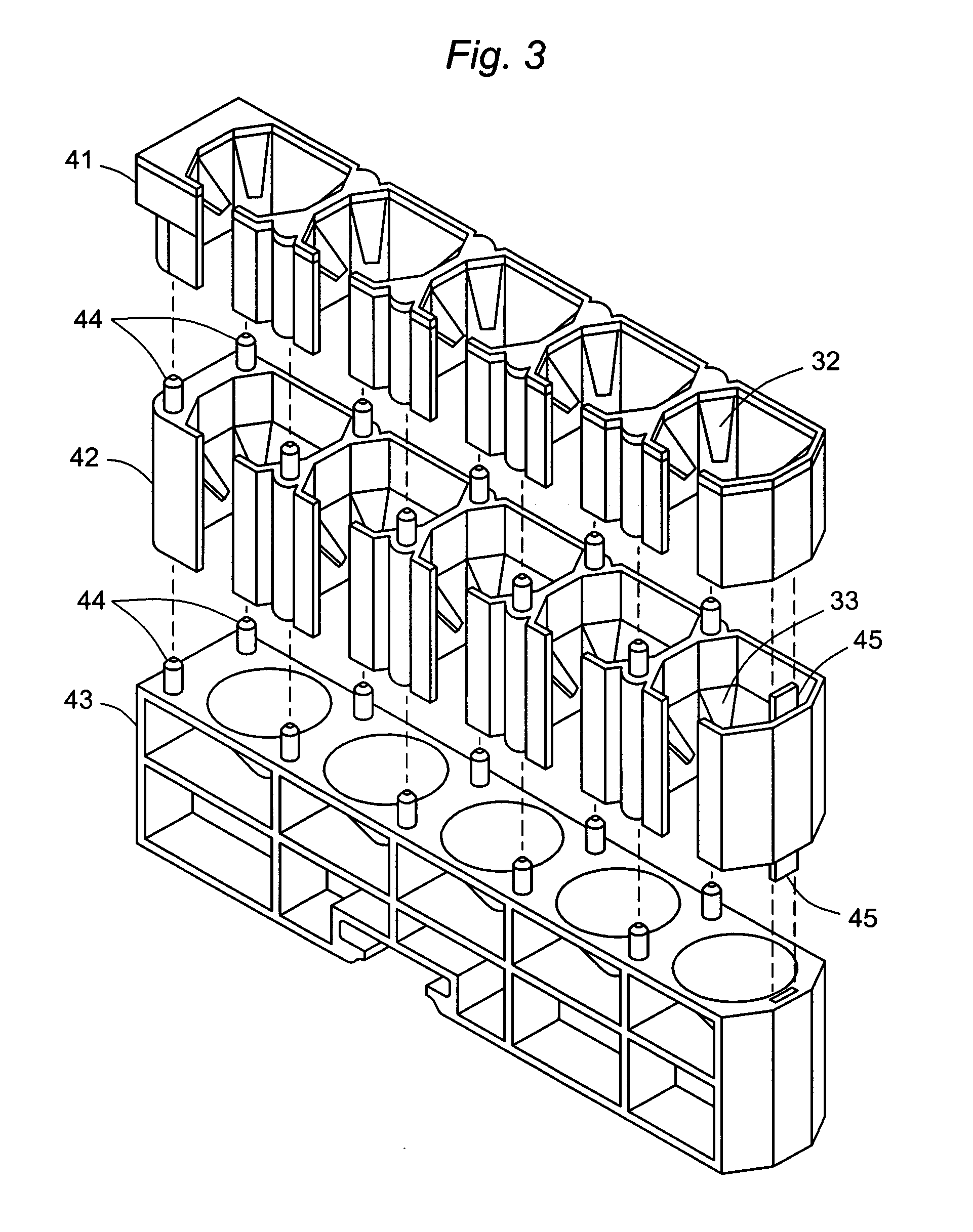
[0011]The sample rack is illustrated in three views in FIGS. 1, 2, and 3. Viewing the side elevation of FIG. 1 and the top view of FIG. 2 together, the sample rack 11 is a molded structure that includes five sample tube chambers 12, each chamber open at the top 13 and closed at the bottom with a tapering conical-shaped floor 14 that has an aperture 15 at its center. Each chamber is generally octagonal in cross section, as is most clearly seen in FIG. 2, with eight wall sections including a rear wall 16, a forward wall 17, two side walls formed by lateral partitions 18 that separate the chambers, and four corner walls 19. The forward wall 17 of each chamber...


PUM


Abstract

A tube rack for holding and transporting sample tubes or other liquids in an automated analyzer is built to accommodate tubes of different sizes in a stable aligned configuration, the rack containing a row of parallel open-top tube chambers, each chamber containing two sets of resilient tabs integrally molded with the chamber walls and at different heights in the chamber.

Description

BACKGROUND OF THE INVENTION[0001]1. Field of the Invention[0002]This invention resides in the field of specimen sampling equipment and liquid handling equipment in general for automated analyzers, with particular attention to racks in which sample tubes are held in such an analyzer.[0003]2. Description of the Prior Art[0004]Laboratory analyzers for the automated analysis of a multitude of biological specimens typically include several coordinated liquid transfer systems and one or more movable sample tube racks. These racks hold the sample tubes in position and transport them to each of various positions in the analyzer where different robotic mechanisms are used for liquid addition and withdrawal in the performance of the different functional operations of the analysis. The optimal rack is one that holds the tubes in a stable manner, thereby preventing the tubes from becoming dislodged or their orientation from being changed as the rack is moved within the analyzer, and also one th...

Claims


Application Information

Patent Timeline
Patent Type & Authority Patents(United States)
IPC IPC(8): A47B73/00B01L9/06
CPCB01L9/06B01L2200/025
Inventor JAFARI, NASSERBLECKA, LAWRENCE J.
Owner BIO RAD LAB INC
Why Eureka
Try Eureka